
Polaris

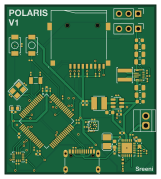
About the Polaris PCB
Polaris is an open source STM32 PCB design by nsreeni07, published on GitHub under the MIT license. It is a 2-layer board measuring 40 × 44.8 mm, with 79 components from 50 distinct parts.
Its main chip is the BMP580, from the STM32 family. Other key parts include the BQ25883RGER, ICM-45686, TPS63070RNMR and LMR51430. By type, the board carries 37 capacitors, 22 resistors, 6 ICs, 4 inductors, 3 connectors and 2 crystals.
It belongs with the power & battery and sensors designs in this gallery.
From the project
A custom-built TVC rocket with a self-designed STM32F722 flight computer (Madgwick AHRS, dual-axis PID, active gimbal correction) for stable, actively-corrected flight.
2. Flight Computer - STM32F722RET6 MicroController - ICM-45686 IMU - BMP580 Barometer - BQ25883 Battery Charger - 4 channel servo PWM - microSD Card for logging
3. Launchpad - ESP32 MicroController - 2 control arms that hold and release the rocket at liftoff - 2 ESP32-CAM modules that record the launch - RGB strip light and 4 2812 LEDs for pad status/lighting - Water deluge system for pad deck
Main components on the Polaris
Polaris bill of materials (BOM)
79 components, 50 distinct parts — part numbers from the project's BOM.
| Qty | Part | Footprint | Refs |
|---|---|---|---|
| 1 | BMP580 Bosch(博世) | LGA-10_L2.0-W2.0-P0.50-TL_BMP580 | U1 |
| 1 | BQ25883RGER STM32F722RETx | LQFP-64_10x10mm_P0.5mm | U2 |
| 1 | ICM-45686 TDK InvenSense(应美盛) | LGA-14_L3.0-W2.5-P0.50-TL | U3 |
| 1 | TPS63070RNMR TI(德州仪器) | VQFN-15_L3.0-W2.5-P0.50-BL | U4 |
| 1 | BQ25883RGER TI(德州仪器) | VFQFPN-24_L4.0-W4.0-P0.50-BL-EP2.8 | U5 |
| 1 | LMR51430 | SOT-23-6 | U6 |
| 1 | X322525MOB4SI YXC(扬兴晶振) | CRYSTAL-SMD_4P-L3.2-W2.5-BL | X1 |
| 1 | Q13FC13500004 Q13FC1350000400 EPSON(爱普生) | FC-135R_L3.2-W1.5 | X2 |
| 1 | SCREW_TERMINAL_01X02 Screw_Terminal_01x02 | TerminalBlock_Xinya_XY308-2.54-2P_1x02_P2.54mm_Horizontal | J1 |
| 2 | CONN_01X03 Conn_01x03 | PinHeader_1x03_P2.54mm_Vertical | J2, J3 |
| 1 | TF-01A 韩国韩荣 | TF-SMD_TF-01A | Card1 |
| 2 | TS-1088-AR02016 XUNPU(讯普) | SW-SMD_L3.9-W3.0-P4.45 | SW1, SW2 |
| 1 | TYPE-C 16PIN 2MD(073) TYPE-C 16PIN 2MD SHOU HAN(首韩) | USB-C-SMD_TYPE-C-16PIN-2MD-073 | USB1 |
| 1 | LED | LED_0402_1005Metric | D1 |
| 1 | 1uH | L2520 | L1 |
| 1 | 1.5uH | IND-SMD_L4.0-W4.0-A | L2 |
| 1 | 5.6uH | IND-SMD_L3.0-W3.0 | L3 |
| 1 | FCM1608KF-601T03 TAI-TECH(台庆) | L0603 | L4 |
| 3 | 1UF 1uF | C_0402_1005Metric | C1, C29, C30 |
| 2 | 10UF 10uF | C_0603_1608Metric | C2, C9 |
Show 30 more
| Qty | Part | Footprint | Refs |
|---|---|---|---|
| 1 | 10UF 44uF | C_0402_1005Metric | C3 |
| 1 | 47NF 10uF | C_0201_0603Metric | C4 |
| 1 | 10UF 47nF | C_0402_1005Metric | C5 |
| 1 | 44UF 10uF | C_0603_1608Metric | C6 |
| 2 | 10UF 10uF | C_0805_2012Metric | C7, C8 |
| 1 | 22UF 100nF | C_0201_0603Metric | C10 |
| 1 | 22UF 10uF | C_0603_1608Metric | C11 |
| 1 | 10UF 22uF | C_0805_2012Metric | C12 |
| 1 | 22UF 22uF | C_0805_2012Metric | C13 |
| 1 | 100NF 22uF | C_0805_2012Metric | C14 |
| 1 | 100NF 2.2uF | C_0603_1608Metric | C15 |
| 1 | 2.2UF 100nF | C_0201_0603Metric | C16 |
| 2 | 22UF 22uF | C_0402_1005Metric | C17, C18 |
| 9 | 100NF 100nF | C_0201_0603Metric | C19, C20, C21, C22, C24, C25, C26, C27 +1 |
| 1 | 100NF 2.2uF | C_0201_0603Metric | C23 |
| 1 | 1UF 100nF | C_0402_1005Metric | C28 |
| 1 | 10UF 1uF | C_0402_1005Metric | C31 |
| 1 | 2.2UF 10uF | C_0201_0603Metric | C32 |
| 2 | 20PF 20pF | C_0201_0603Metric | C33, C34 |
| 2 | 6.8PF 6.8pF | C_0201_0603Metric | C35, C36 |
| 2 | 5.1K 5.1k | R_0201_0603Metric | R1, R2 |
| 1 | 10K | R_0201_0603Metric | R3 |
| 1 | 5.23K 10K | R_0201_0603Metric | R4 |
| 1 | 30.1K 10K | R_0201_0603Metric | R5 |
| 12 | 10K | R_0201_0603Metric | R6, R7, R11, R12, R13, R16, R17, R18 +4 |
| 1 | 10K 5.23K | R_0201_0603Metric | R8 |
| 1 | 10K 30.1K | R_0201_0603Metric | R9 |
| 1 | 10K 383 | R_0201_0603Metric | R10 |
| 1 | 100K | R_0402_1005Metric | R14 |
| 1 | 22.1K | R_0201_0603Metric | R15 |
Polaris design files
The KiCad project lives in the nsreeni07/Polaris repository on GitHub; these links point at the commit this page was built from.
Polaris: common questions
What microcontroller does the Polaris use?
The Polaris is built around the BMP580, from the STM32 family.
How big is the Polaris PCB?
The Polaris measures 40 × 44.8 mm, has 2 copper layers and is 1.6 mm thick.
How many components are on the Polaris?
79 components, from 50 distinct parts, with part numbers taken from the project's own BOM. The full bill of materials is listed on this page.
Where can I download the Polaris design files?
From the nsreeni07/Polaris repository on GitHub, which has the KiCad layout, the schematic and the BOM; the links under Design files point to each one.
Can I use the Polaris design in my own project?
Yes, under the terms of its MIT license, which nsreeni07 chose for the repository.
Can I test firmware for the Polaris without the hardware?
Yes. HardLabs builds a simulation of the board from its netlist and BOM, so you can run and debug STM32 firmware against it before you order a PCB.
Similar boards
 STM32
LumenPnP Motherboard
opulo-inc
149 × 95 mm296 parts4LCC-BY-SA-4.03.7k STM32
Type g
google
169 × 30 mm24 parts2LApache-2.02.9k STM32
Base
52.3 × 52.3 mm36 parts2LApache-2.02.9k STM32
Main panel
234 × 84 mm26 parts4LApache-2.02.9k STM32
Type a
150 × 30 mm14 parts2LApache-2.02.9k STM32
Type c
188 × 30 mm17 parts2LApache-2.02.9k