
Mini-Power-Gauge

About the Mini-Power-Gauge PCB
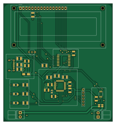
Mini-Power-Gauge is an open source AVR/Arduino PCB design by oct-karim, published on GitHub. It is a 2-layer board measuring 92.1 × 99.4 mm, with 54 components from 41 distinct parts.
Its main chip is the ATMEGA328P-A, from the AVR/Arduino family. Other key parts include the PCF8574AT and INA226. By type, the board carries 18 test points, 11 resistors, 9 capacitors, 5 connectors, 4 diodes and 3 ICs.
It belongs with the displays & leds designs in this gallery.
From the project
A mini power gauge that mesures current and voltage.
A simple PCB, functional and efficient. For monitoring current, voltage and power.
This simple power gauge, controlled by the ATmega328P microcontroller has a voltage range of 0-36V and a current range of 0-3A. The footprints have been chosen to be easy to solder. And the components are widely available.
Main components on the Mini-Power-Gauge
Mini-Power-Gauge bill of materials (BOM)
54 components, 41 distinct parts — part numbers from the project's BOM.
| Qty | Part | Footprint | Refs |
|---|---|---|---|
| 1 | ATMEGA328P-A ATmega328P-A | TQFP-32_7x7mm_P0.8mm | U1 |
| 1 | PCF8574AT | SOIC-16W_7.5x10.3mm_P1.27mm | U2 |
| 1 | INA226 | VSSOP-10_3x3mm_P0.5mm | U3 |
| 1 | 2N3904 | TO-92_Inline_Wide_EBC | Q1 |
| 1 | 16MHZ 16MHz | Crystal_SMD_2012-2Pin_2.0x1.2mm_HandSoldering | X1 |
| 1 | USB_C_RECEPTACLE_POWERONLY_6P USB_C_Receptacle_PowerOnly_6P | USB_C_Receptacle_GCT_USB4125-xx-x-0190_6P_TopMnt_Horizontal | J1 |
| 1 | CONN_01X06_SOCKET Conn_01x06_Socket | PinSocket_1x06_P2.54mm_Vertical | J2 |
| 2 | 3.5MM 3.5mm | ScrewTerminal_1x02_P3.5mm_Horizontal_Black | J3, J4 |
| 1 | CONN_01X16_SOCKET Conn_01x16_Socket | PinSocket_1x16_P2.54mm_Vertical | J5 |
| 1 | HY1602E | WC1602A | DS1 |
| 1 | LED_R | TestPoint-0.75mm | TP1 |
| 1 | LED_G | TestPoint-0.75mm | TP2 |
| 1 | Led_B | TestPoint-0.75mm | TP3 |
| 1 | SCL_INA226 | TestPoint-0.75mm | TP4 |
| 1 | SDA_INA226 | TestPoint-0.75mm | TP5 |
| 1 | 5V | TestPoint-0.75mm | TP6 |
| 1 | INPUT | TestPoint-0.75mm | TP7 |
| 1 | OUTPUT | TestPoint-0.75mm | TP8 |
| 1 | P1 | TestPoint-0.75mm | TP9 |
| 1 | P3 | TestPoint-0.75mm | TP10 |
Show 21 more
| Qty | Part | Footprint | Refs |
|---|---|---|---|
| 1 | P5 | TestPoint-0.75mm | TP11 |
| 1 | P7 | TestPoint-0.75mm | TP12 |
| 1 | P0 | TestPoint-0.75mm | TP13 |
| 1 | P2 | TestPoint-0.75mm | TP14 |
| 1 | P4 | TestPoint-0.75mm | TP15 |
| 1 | P6 | TestPoint-0.75mm | TP16 |
| 2 | Mesure | TestPoint-0.75mm | TP17, TP18 |
| 1 | RED | LED_1206_3216Metric_Pad1.42x1.75mm_HandSolder | D1 |
| 1 | GREEN | LED_1206_3216Metric_Pad1.42x1.75mm_HandSolder | D2 |
| 1 | BLUE | LED_1206_3216Metric_Pad1.42x1.75mm_HandSolder | D3 |
| 1 | SMAJ5.0A | D_SMA | D4 |
| 1 | 300Ω@100MHz | Ferrite_1210_3225Metric_Pad1.42x2.65mm_BigPads | FB1 |
| 6 | 100N 100n | C_1210_3225Metric_Pad1.33x2.70mm_HandSolder | C1, C2, C3, C7, C8, C9 |
| 2 | 22P 22p | C_1210_3225Metric_Pad1.33x2.70mm_HandSolder | C4, C6 |
| 1 | 10µ | C_1210_3225Metric_Pad1.33x2.70mm_HandSolder | C5 |
| 2 | 5.1K | R_1210_3225Metric_Pad1.30x2.65mm | R1, R2 |
| 1 | 10K 10k | R_1210_3225Metric_Pad1.30x2.65mm | R3 |
| 3 | 470 | R_1210_3225Metric_Pad1.30x2.65mm | R4, R5, R6 |
| 2 | 4.7K 4.7k | R_1210_3225Metric_Pad1.30x2.65mm | R7, R8 |
| 2 | 1k | R_1210_3225Metric_Pad1.30x2.65mm | R9, R10 |
| 1 | 0,02 | R_Shunt_Ohmite_LVK12 | R11 |
Mini-Power-Gauge design files
The KiCad project lives in the oct-karim/Mini-Power-Gauge repository on GitHub; these links point at the commit this page was built from.
- LayoutPCB/Power_Gauge_PCB.kicad_pcb
- SchematicPCB/Power_Gauge_PCB.kicad_sch
- BOMbom.csv
Mini-Power-Gauge: common questions
What microcontroller does the Mini-Power-Gauge use?
The Mini-Power-Gauge is built around the ATMEGA328P-A, from the AVR/Arduino family.
How big is the Mini-Power-Gauge PCB?
The Mini-Power-Gauge measures 92.1 × 99.4 mm, has 2 copper layers and is 1.6 mm thick.
How many components are on the Mini-Power-Gauge?
54 components, from 41 distinct parts, with part numbers taken from the project's own BOM. The full bill of materials is listed on this page.
Where can I download the Mini-Power-Gauge design files?
From the oct-karim/Mini-Power-Gauge repository on GitHub, which has the KiCad layout, the schematic and the BOM; the links under Design files point to each one.
Can I use the Mini-Power-Gauge design in my own project?
The repository has no license, so all rights stay with oct-karim. Use it as a reference, and ask the author before reusing the design.
Can I test firmware for the Mini-Power-Gauge without the hardware?
Yes. HardLabs builds a simulation of the board from its netlist and BOM, so you can run and debug AVR/Arduino firmware against it before you order a PCB.
Similar boards
 AVR/Arduino
Redox keyboard
mattdibi
162.2 × 126.5 mm77 parts2LMIT2.0k AVR/Arduino
ModuleV450
stuartpittaway
30 × 61.4 mm39 parts2LCC-BY-NC-4.01.1k AVR/Arduino
V4
30 × 50 mm38 parts2LCC-BY-NC-4.01.1k AVR/Arduino
Discipline
coseyfannitutti
304.9 × 122.8 mm170 parts2LCC-BY-NC-4.01.0k AVR/Arduino
Megadesk
gcormier
41.7 × 32.2 mm23 parts2LGPL-3.0818 AVR/Arduino
Easyduino Atmega Nano
Hanqaqa
43.4 × 18 mm30 parts4LCERN-OHL-P-2.0746