
87 open source boards using the INA226
Real designs built with the INA226, from public GitHub projects: a quick way to see how others power, decouple and connect it. Each board comes with its KiCad files, full parts list and a render — and you can simulate its firmware on HardLabs.
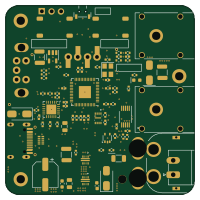 RP2040/RP2350
PocketPD HW
CentyLab
50 × 50 mm81 parts2LCC-BY-SA-4.0196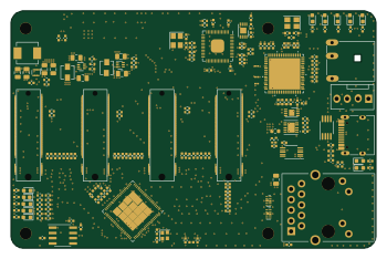 RP2040/RP2350
CM4ClusterHat
will127534
87.3 × 56.7 mm240 parts4LMIT95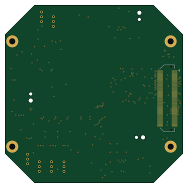
Axiom Micro Mainboard
anuejn
94 × 94 mm202 parts4LNo license38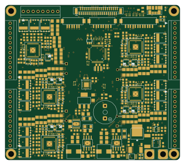
Powerboard v1
TIGERs-Mannheim
90 × 80 mm372 parts4LCustom license9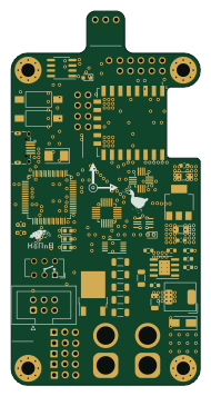 ESP8266
Flight controller v2
Eryk-Mozdzen
45 × 89 mm108 parts4LNo license9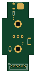
Radio Bottom
mattronix
30 × 64 mm12 parts2LCERN-OHL-W-2.08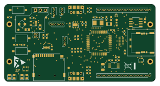 STM32
Node base
LanternD
78 × 40 mm73 parts2LApache-2.06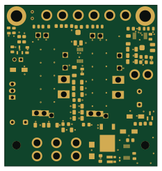
Power supply
matthieuvigne
58 × 61.1 mm77 parts4LGPL-3.05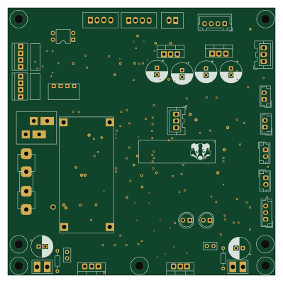
Balancer
kwiecinski
99.5 × 99.5 mm165 parts2LMIT3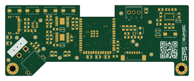 ESP32
SUMEC MK V Pro
bismarx-v1
97 × 37.5 mm120 parts4LNo license3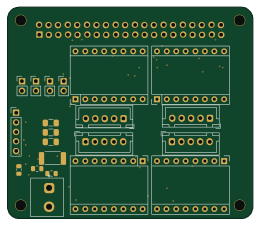
PiScope
cutec-chris
65 × 56 mm41 parts2LNo license3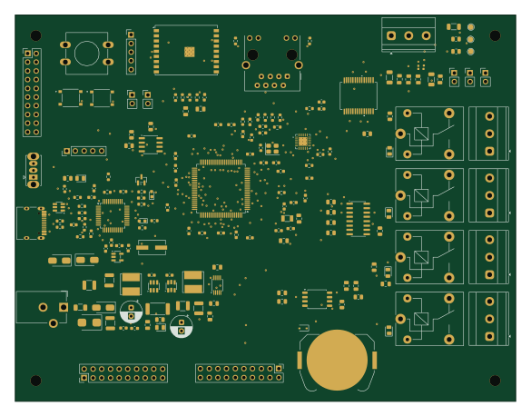 ESP32
IoT Gateway STM32F407VGTx
minhtenlado
146.1 × 112.6 mm184 parts6LNo license2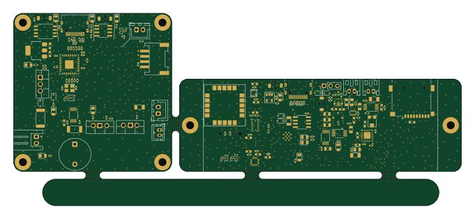 RP2040/RP2350
IGNRocketOrderFile
wasa-rockoon
170 × 73 mm182 parts2LMIT1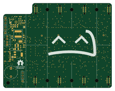 ESP32
SlimeVR Dock
Skaut0071
100 × 78 mm151 parts2LCERN-OHL-P-2.01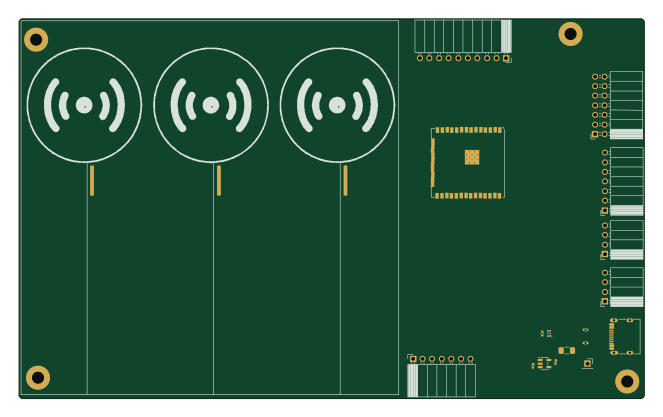 ESP32
Intelligent-Traffic-Simulator
LimesKey
165.5 × 100.5 mm148 parts4LApache-2.01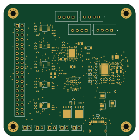
VikramSat Electrical-Power-Sub-System
Rishaan2202
72 × 72.1 mm123 parts2LMIT1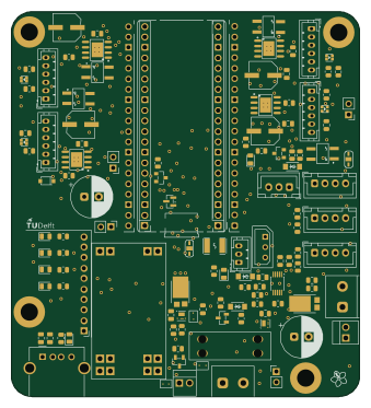
Mirte master bottom
mirte-robot
84.3 × 93.1 mm109 parts4LCERN-OHL-P-2.01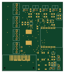 ESP32
Water cooling controller
diablo4338
55.6 × 63.5 mm84 parts2LMIT1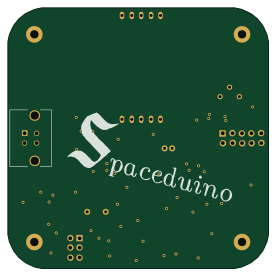 AVR/Arduino
Spaceduino
UWCubeSat
69 × 69 mm81 parts2LMIT1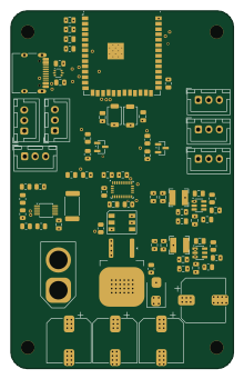 ESP32
MADHEX-v2
DEFOR111
53 × 85 mm75 parts4LNo license1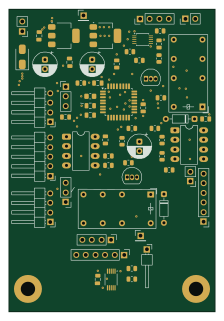 STM32
Electronicload
GM4AJK
54.5 × 80 mm62 parts4LNo license1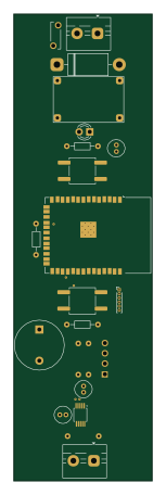 ESP32
Power Monitor V2.1
Filips-Talums
33.7 × 113.8 mm21 parts2LNo license1- schematic only · 16 partsAVR/Arduino
RotorRig-V1.0
GrzegorzG7
16 partsCC-BY-NC-4.01 - schematic only · 14 partsESP32
Syzygy
AsamaeS
14 partsMIT1 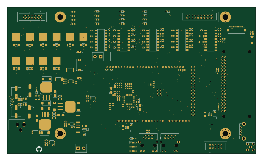 AVR/Arduino
MEP MAXI 85V-1 REV 2 Interface Board
JGilcreast
221.5 × 130.8 mm323 parts4LNo license0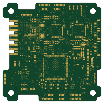 STM32
Sss opr3-v1 (1)
Space-and-Satellite-Systems-UC-Davis
90 × 90 mm267 parts4LNo license0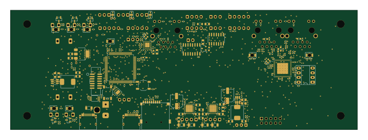 STM32
Factory in a box
klaus-liebler
188 × 65 mm264 parts4LNo license0 NXP
NAA-Measurment-Carrier-System
pmamatis
40 × 293.4 mm261 parts4LMIT0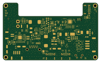 STM32
KigEyes
jrymk
100 × 60 mm256 parts4LCERN-OHL-S-2.00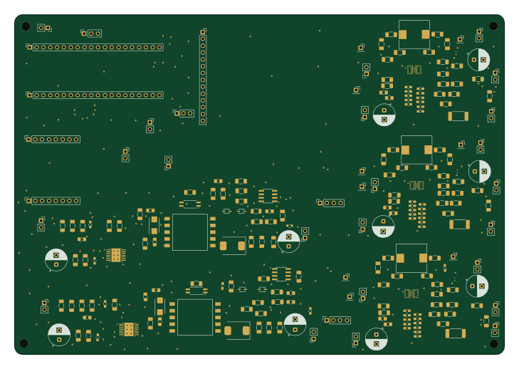
EDL Project 2026
segf4u1t-139
182 × 126.2 mm237 parts2LNo license0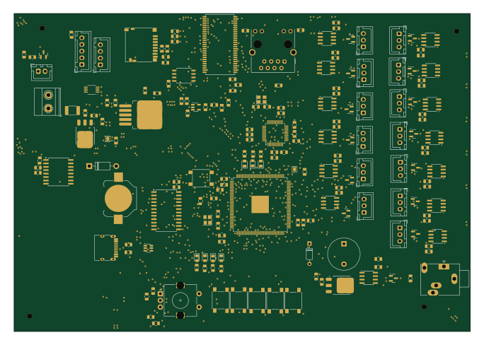
CoreLight
llextv
170.7 × 119 mm192 parts4LNo license0 PIC
SensorHub
komoro13
130 parts2LNo license0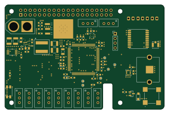 STM32
UYDUTEPE
emirhanuluakan
85 × 56 mm93 parts6LCERN-OHL-W-2.00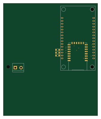 ESP8266
Prueba placa2
FranMald
83.4 × 99.1 mm83 parts2LNo license0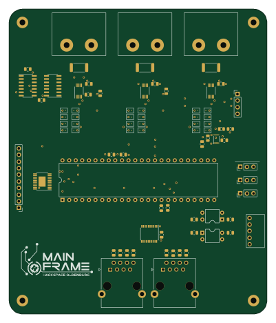 NXP
Mainframe led tube
lordiii
99.1 × 116.8 mm79 parts2LGPL-3.00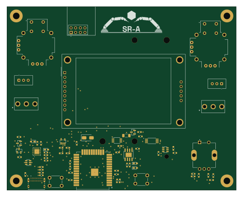 ESP32
Bonk
tyke01
125 × 100 mm72 parts4LNo license0
How designs wire the INA226
Read from the KiCad layouts of 61 open source designs, one per repository: what each pin of the INA226 connects to, and the resistors, capacitors and other passives placed on it.
- The SCL pin has a pull-up to 3.3V on 46 of 61 designs, most often 4.7 kΩ (then 10 kΩ).
- The SDA pin has a pull-up to 3.3V on 44 of 61 designs, most often 4.7 kΩ (then 10 kΩ).
- The VS pin has a decoupling capacitor on 43 of 61 designs, most often 100 nF (then 10 µF).
- The A1 pin is tied to GND on 46 of 61 designs (not connected on 3, 3.3V on 4, a signal on 8).
| Pin | Connected to | Parts on the pin |
|---|---|---|
| A1pin 1 | Connected to: GND 75% | — |
| A0pin 2 | Connected to: GND 74% | — |
| SDApin 4 | Connected to: The microcontroller 57%, a connector 36%, INA226 23% |
|
| SCLpin 5 | Connected to: The microcontroller 57%, a connector 38%, INA226 23% |
|
| VSpin 6 | Connected to: 3.3V 80% · a signal 20% |
|
| GNDpin 7 | Connected to: GND 98% | — |
| VBUSpin 8 | Connected to: Signal 59% · 3.3V 41% |
|
| VIN-pin 9 | Connected to: Signal 68% · 12V 22% |
|
| VIN+pin 10 | Connected to: Signal 69% · 24V 27% |
|
1 more pin varies from design to design. Connections count pins, parts count designs; values in brackets are how many parts had that value. Designs read include Gp4-stqfn20-thermal by azonenberg, PocketPD HW by CentyLab, Iob characterization v02 by azonenberg and CM4ClusterHat by will127534.
The INA226 in open source designs
The gallery holds 87 open source boards using the INA226 from 65 GitHub repositories; a typical one measures about 84.3 × 70.2 mm and carries around 79 components.
58% are two-layer designs, the rest use four layers or more, and 48% carry an open source license.
The most starred is Gp4-stqfn20-thermal by azonenberg.
Parts used alongside the INA226
Microcontrollers on boards using the INA226
What boards using the INA226 are built for
INA226: common questions
Where can I find a INA226 reference design?
Each of the 87 boards on this page is a real design using the INA226. Open one to see how it is wired up, with the full BOM, a render of the layout and links to its KiCad files.
What pull-up resistor is used on the INA226 SCL pin?
The SCL pin has a pull-up to 3.3V on 46 of 61 designs, most often 4.7 kΩ (then 10 kΩ). Counted from the KiCad layouts of 61 open source designs using the INA226.
What pull-up resistor is used on the INA226 SDA pin?
The SDA pin has a pull-up to 3.3V on 44 of 61 designs, most often 4.7 kΩ (then 10 kΩ). Counted from the KiCad layouts of 61 open source designs using the INA226.
What decoupling capacitors do designs use on the INA226 VS pin?
The VS pin has a decoupling capacitor on 43 of 61 designs, most often 100 nF (then 10 µF). Counted from the KiCad layouts of 61 open source designs using the INA226.
What parts are used alongside the INA226?
The ESP32-S3-WROOM-1, USBLC6-2SC6, AMS1117-3.3, AP2112K-3.3 and W25Q128JVS appear in the most repositories here.
Which microcontrollers do boards using the INA226 use?
Most are built on ESP32 (31), STM32 (9), AVR/Arduino (8) and RP2040/RP2350 (6).
How big is a typical board using the INA226?
The median is 84.3 × 70.2 mm, and 58% are two-layer designs.
What is the most popular open source board using the INA226?
By GitHub stars, Gp4-stqfn20-thermal by azonenberg, with 260 stars.
Can I simulate one of these boards using the INA226 before building it?
Yes. HardLabs turns a board's netlist and BOM into a working simulation, so you can boot and test firmware against it with no hardware on your desk.