
Charger


About the Charger PCB
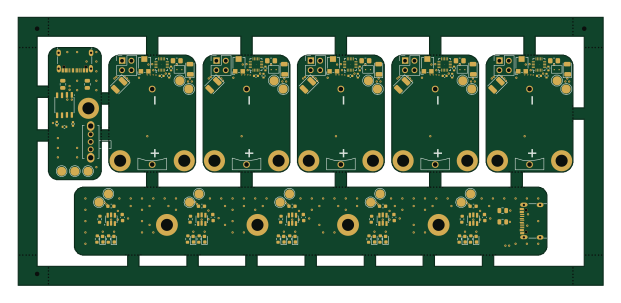
Charger is an open source PCB design by PHS-SMCS, published on GitHub. It is a 2-layer board measuring 125.3 × 18 mm, with 53 components from 8 distinct parts.
Other key parts include the TP4057. By type, the board carries 17 resistors, 10 diodes, 10 capacitors and 5 ICs.
It belongs with the power & battery designs in this gallery.
From the project
Falconia Beacon is an ATTINY816-based, CR2032-powered LED beacon board used to make the Falconia rover visible to the SMCS Pi-in-the-sky satellite.
Falconia Beacon is an ATTINY816-based, CR2032-powered LED beacon board used to make the Falconia rover visible to the SMCS Pi-in-the-sky satellite.
- Blinks onboard LEDs so the satellite can detect the rover location. - Uses a potentiometer to enable or disable the blinking program. - Supports I2C control at address 0x42.
- PCB/ Hardware design and manufacturing assets: - KiCad schematic and PCB files - 3D models and custom footprints/symbol libraries - Panelization and production outputs
Main components on the Charger
Charger bill of materials (BOM)
53 components, 8 distinct parts.
| Qty | Part | Footprint | Refs |
|---|---|---|---|
| 5 | TP4057 | TSOT-23-6 | U1, U2, U3, U4, U5 |
| 10 | YTC1P-6030-01 | SMD-1_BD2.0-H10.0 | +BAT1, +BAT2, +BAT3, +BAT4, +BAT5, -BAT1, -BAT2, -BAT3 +2 |
| 1 | TYPE-C_16PIN_2MD_073_ | USB-C-SMD_TYPE-C-6PIN-2MD-073 | USB1 |
| 10 | LED | LED_0603_1608Metric | D1, D2, D3, D4, D5, D6, D7, D8 +2 |
| 10 | 10uF | C_0603_1608Metric | C1, C2, C3, C4, C5, C6, C7, C8 +2 |
| 10 | 1kΩ | R_0603_1608Metric | R1, R2, R4, R5, R7, R8, R10, R11 +2 |
| 5 | 20kΩ | R_0603_1608Metric | R3, R6, R9, R12, R15 |
| 2 | 5.1kΩ | R_0805_2012Metric | R16, R17 |
Charger design files
The KiCad project lives in the PHS-SMCS/Falconia-Beacon repository on GitHub; these links point at the commit this page was built from.
- LayoutPCB/Charger/charger.kicad_pcb
- SchematicPCB/Charger/charger.kicad_sch
Charger: common questions
How big is the Charger PCB?
The Charger measures 125.3 × 18 mm, has 2 copper layers and is 1.6 mm thick.
How many components are on the Charger?
53 components, from 8 distinct parts. The full bill of materials is listed on this page.
Where can I download the Charger design files?
From the PHS-SMCS/Falconia-Beacon repository on GitHub, which has the KiCad layout and the schematic; the links under Design files point to each one.
Can I use the Charger design in my own project?
The repository has no license, so all rights stay with PHS-SMCS. Use it as a reference, and ask the author before reusing the design.
More boards in Falconia-Beacon
Similar boards
EinkPDA screen
TalismanDesign
95 × 54 mm27 parts2LApache-2.02.0k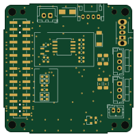
Stack chan
stack-chan
50 × 50 mm33 parts2LApache-2.01.7k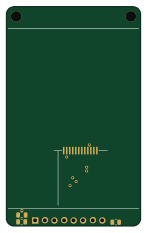
Display Carrier
AxxAxx
35.6 × 58.2 mm5 parts2LGPL-3.01.7k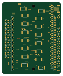
Module 16S PassiveBalanceAddOn
stuartpittaway
61 × 74 mm86 parts2LCC-BY-NC-4.01.1k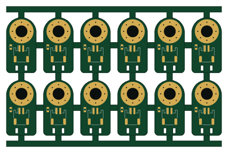
TemperaturePCB PANEL
116 × 75.5 mm178 parts2LCC-BY-NC-4.01.1k
ProgrammingAdapter
10.5 × 83 mm3 parts2LCC-BY-NC-4.01.1k