
IMU Dev Board

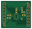
About the IMU Dev Board
IMU Dev Board is an open source PCB design by Purdue-Space-Program, published on GitHub. It is a 2-layer board measuring 25.5 × 23 mm, with 12 components from 6 distinct parts.
Other key parts include the BMI088. By type, the board carries 4 diodes, 3 capacitors, 2 connectors, 2 resistors and 1 IC.
It belongs with the sensors and dev boards & breakouts designs in this gallery.
From the project
Boards and other components for R4
��# PSPLR4Avionics_Hardware
Main components on the IMU Dev Board
IMU Dev Board bill of materials (BOM)
12 components, 6 distinct parts.
| Qty | Part | Footprint | Refs |
|---|---|---|---|
| 1 | BMI088 | QFN_BMI085_BOS | U1 |
| 2 | Conn_01x08_Pin | PinHeader_1x08_P2.54mm_Vertical | J1, J2 |
| 4 | D_Zener | D_SOD-882 | D1, D2, D3, D4 |
| 2 | 100nF | C_0805_2012Metric | C1, C2 |
| 1 | 1uF | C_0805_2012Metric | C3 |
| 2 | 22 | R_0805_2012Metric | R1, R2 |
IMU Dev Board design files
The KiCad project lives in the Purdue-Space-Program/PSPL_R4_Avionics_Hardware repository on GitHub; these links point at the commit this page was built from.
IMU Dev Board: common questions
How big is the IMU Dev Board?
The IMU Dev Board measures 25.5 × 23 mm, has 2 copper layers and is 1.69 mm thick.
How many components are on the IMU Dev Board?
12 components, from 6 distinct parts. The full bill of materials is listed on this page.
Where can I download the IMU Dev Board design files?
From the Purdue-Space-Program/PSPL_R4_Avionics_Hardware repository on GitHub, which has the KiCad layout and the schematic; the links under Design files point to each one.
Can I use the IMU Dev Board design in my own project?
The repository has no license, so all rights stay with Purdue-Space-Program. Use it as a reference, and ask the author before reusing the design.
More boards in PSPL_R4_Avionics_Hardware
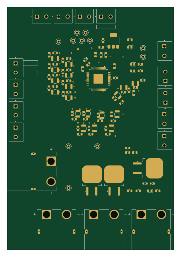
BMS 1.1
89.5 × 130 mm113 parts2LNo license2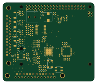
Flight computer
78 × 67 mm102 parts4LNo license2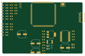 STM32
Stm
71.4 × 46.2 mm69 parts2LNo license2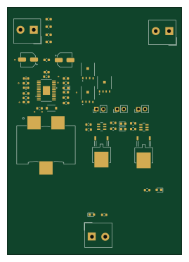 NXP
Power systems
65.5 × 93 mm50 parts4LNo license2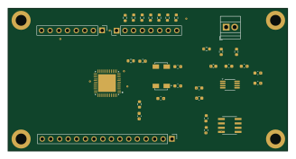
DAQ dev board
82 × 42 mm38 parts2LNo license2
MegaTC dev board
34.3 × 34.3 mm35 parts4LNo license2
Pyro
34.5 × 32.3 mm15 parts2LNo license2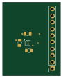
Magnetometer Dev Board
22 × 28 mm5 parts2LNo license2
Similar boards
Sensor smd
scottbez1
40 × 20 mm5 parts2LApache-2.04.2k
Sensors
StuckAtPrototype
15.2 × 9 mm14 parts4LApache-2.03.8k
Microphone
Mentra-Community
5.5 × 6.1 mm6 parts2LMIT1.2k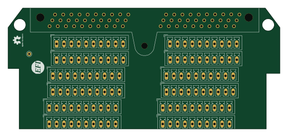
Breakout 60pin EEC-IV
rusefi
139.7 × 62.2 mm15 parts2LGPL-3.01.2k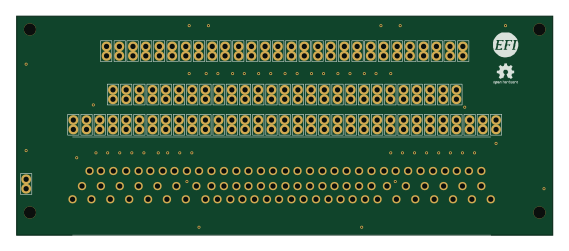
88 Pin Vag Breakout
142 × 58 mm91 parts2LGPL-3.01.2k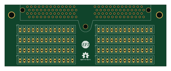
Eecv breakout
140.8 × 53.7 mm9 parts4LGPL-3.01.2k