
SmartClockPi

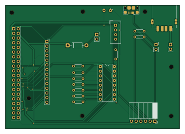
About the SmartClockPi PCB
SmartClockPi is an open source Raspberry Pi PCB design by QinCai-rui, published on GitHub under the GPL-3.0 license. It is a 2-layer board measuring 94.5 × 67.1 mm, with 22 components from 14 distinct parts.
Its main chip is the Raspberry_Pi, from the Raspberry Pi family. Other key parts include the MCP3008 and DHT22. By type, the board carries 11 resistors, 8 connectors, 2 ICs and 1 diode.
It belongs with the displays & leds and sensors designs in this gallery.
From the project
A Raspberry Pi Zero 2 W based smart clock with touchscreen display, environmental sensing, and internet weather integration.
A Raspberry Pi Zero 2 W based smart clock with touchscreen display, environmental sensing, and internet weather integration.
This project uses KiCad for PCB design. The files are located in the PCB/ directory. You can open them with KiCad to view the schematics and PCB layout. These are the screenshots of the PCB and schematics:
I wanted a smart clock that could display the time, date, indoor temperature, humidity, and outdoor weather conditions. I also wanted it to have a touchscreen interface for easy interaction. The Raspberry Pi Zero 2 W was chosen for its compact size and sufficient…
Main components on the SmartClockPi
SmartClockPi bill of materials (BOM)
22 components, 14 distinct parts — part numbers from the project's BOM.
| Qty | Part | Footprint | Refs |
|---|---|---|---|
| 1 | MCP3008 | DIP-16_W7.62mm_Socket | U2 |
| 1 | DHT22 | Aosong_DHT11_5.5x12.0_P2.54mm | U3 |
| 1 | Raspberry_Pi | PinHeader_2x20_P2.54mm_Vertical | J1 |
| 1 | DS3231 RTC module | PinSocket_1x06_P2.54mm_Horizontal | J2 |
| 1 | ILI9488 SPI TFT touchscreen | PinSocket_1x14_P2.54mm_Vertical | J3 |
| 1 | USB_B_Micro | USB_Micro-B_Amphenol_10118193-0001LF_Horizontal | J5 |
| 1 | USB_A | USB_A_Receptacle_GCT_USB1046 | J6 |
| 1 | microUSB IN | PinSocket_1x02_P2.54mm_Vertical | J7 |
| 1 | USB-A OUT | PinSocket_1x02_P2.54mm_Vertical | J8 |
| 1 | PWR IN | PinSocket_1x02_P2.54mm_Vertical | J9 |
| 1 | 1N4001 | D_DO-41_SOD81_P10.16mm_Horizontal | D1 |
| 1 | LDR07 | R_LDR_5.2x5.2mm_P3.5mm_Horizontal | R1 |
| 1 | 10kΩ | R_Axial_DIN0204_L3.6mm_D1.6mm_P5.08mm_Horizontal | R2 |
| 9 | 4.7kΩ | R_Axial_DIN0204_L3.6mm_D1.6mm_P5.08mm_Horizontal | R3, R4, R5, R6, R7, R8, R9, R12 +1 |
SmartClockPi design files
The KiCad project lives in the QinCai-rui/SmartClockPi repository on GitHub; these links point at the commit this page was built from.
- LayoutPCB/smartclockpi.kicad_pcb
- SchematicPCB/smartclockpi.kicad_sch
- BOMSmartClockPi-bom.csv
SmartClockPi: common questions
What microcontroller does the SmartClockPi use?
The SmartClockPi is built around the Raspberry_Pi, from the Raspberry Pi family.
How big is the SmartClockPi PCB?
The SmartClockPi measures 94.5 × 67.1 mm, has 2 copper layers and is 1.6 mm thick.
How many components are on the SmartClockPi?
22 components, from 14 distinct parts, with part numbers taken from the project's own BOM. The full bill of materials is listed on this page.
Where can I download the SmartClockPi design files?
From the QinCai-rui/SmartClockPi repository on GitHub, which has the KiCad layout, the schematic and the BOM; the links under Design files point to each one.
Can I use the SmartClockPi design in my own project?
Yes, under the terms of its GPL-3.0 license, which QinCai-rui chose for the repository.
Can I test firmware for the SmartClockPi without the hardware?
Yes. HardLabs builds a simulation of the board from its netlist and BOM, so you can run and debug Raspberry Pi firmware against it before you order a PCB.
Similar boards
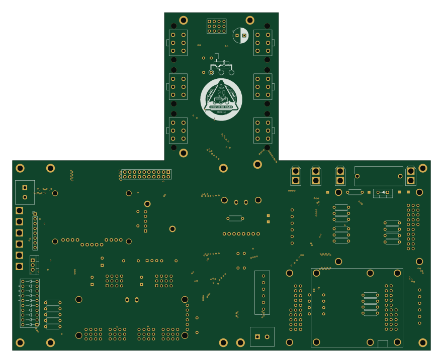 Raspberry Pi
Open source rover
nasa-jpl
220 × 178 mm144 parts2LApache-2.09.7k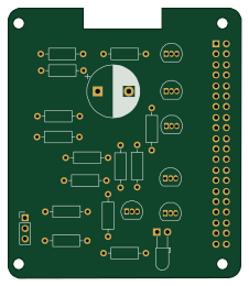 Raspberry Pi
Iot
dotnet
56 × 65 mm24 parts2LMIT2.4k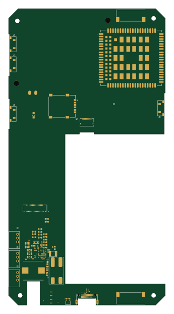 Raspberry Pi
SPIRIT
SPIRIT-org
82 × 155 mm130 parts6LCERN-OHL-S-2.01.3k Raspberry Pi
CM5RevEng
schlae
55 × 40 mm417 parts10LNo license1.0k Raspberry Pi
Haxo hw
cardonabits
102.4 × 211.3 mm38 parts2LCustom license673 Raspberry Pi
Phased
Neumi
75 × 100 mm71 parts2LNo license507