
RoRo80

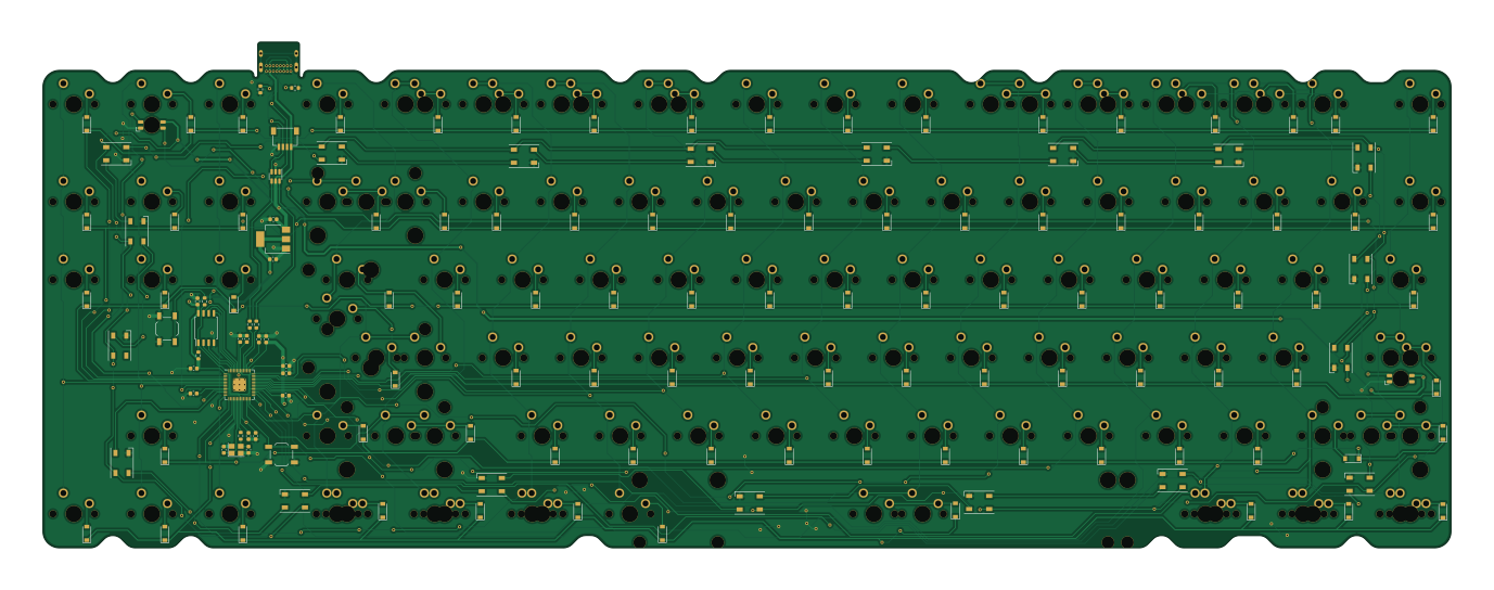
About the RoRo80 PCB
RoRo80 is an open source RP2040/RP2350 PCB design by rarepotato8de, published on GitHub. It is a 2-layer board measuring 343.6 × 123.4 mm, with 248 components from 30 distinct parts.
Its main chip is the RP2040, from the RP2040/RP2350 family. Other key parts include the USBLC6-2SC6, W25Q128JVS and AMS1117-3.3. By type, the board carries 110 diodes, 106 LEDs, 16 capacitors, 7 resistors, 4 ICs and 2 connectors.
It belongs with the keyboards designs in this gallery.
From the project
Custom 80% TKL PCB featuring RP2040, VIAL support. Designed for the "Pete" enthusiast keyboard group.
The RoRo80 is a custom-designed TKL PCB created for the keyboard enthusiast group "Pete". Named as a tribute to the legendary German debt counselor Peter Zwegat (a community inside joke). There have been multiple versions from the RoRo80, which all have been produced and tested! Here are the most recent solder and hotswap versions.
1. First time: Plug the PCB in. A drive named RPI-RP2 will appear. 2. Flash: Drag and drop the firmware.uf2 file into that drive. 3. Subsequent times: Hold the BOOT button, press RESET twice, then release BOOT.
Main components on the RoRo80
RoRo80 bill of materials (BOM)
248 components, 30 distinct parts — part numbers from the project's BOM.
| Qty | Part | Footprint | Refs |
|---|---|---|---|
| 1 | USBLC6-2SC6 | SOT-23-6 | U1 |
| 1 | W25Q128JVS | SOIC-8_5.23x5.23mm_P1.27mm | U2 |
| 1 | RP2040 | RP2040-QFN-56 | U3 |
| 1 | AMS1117-3.3 | SOT-223-3_TabPin2 | U4 |
| 1 | 12MHZ 12MHz | Crystal_SMD_3225-4Pin_3.2x2.5mm | Y1 |
| 1 | USB_C_RECEPTACLE_USB2.0 USB_C_Receptacle_USB2.0 | USB_C_Receptacle_GCT_USB4085 | J1 |
| 1 | AI03_UD ai03_ud | JST-SR-4 | J3 |
| 1 | C318884 RESET | SW_SPST_TL3342 | RESET1 |
| 1 | USB_BOOT | SW_SPST_TL3342 | USB_BOOT1 |
| 2 | MX_SK6812MINI-E | LED_MX_6028R_RUND | LED1, LED2 |
| 80 | 1u | MXOnly-1U-NoLED | MX1, MX2, MX3, MX4, MX5, MX6, MX7, MX8 +72 |
| 1 | 2u | MXOnly-2U-NoLED | MX33 |
| 6 | 1.5U 1.5u | MXOnly-1.5U-NoLED | MX38, MX51, MX98, MX100, MX102, MX104 |
| 9 | 1.25U 1.25u | MXOnly-1.25U-NoLED | MX55, MX71, MX90, MX91, MX92, MX94, MX95, MX96 +1 |
| 1 | ISO_ENTER | MXOnly-ISO-ReversedStabilizers-NoLED | MX56 |
| 2 | 1.75U 1.75u | MXOnly-1.75U-NoLED | MX57, MX84 |
| 2 | 2.25U 2.25u | MXOnly-2.25U-NoLED | MX69, MX72 |
| 1 | 2.75U 2.75u | MXOnly-2.75U-NoLED | MX86 |
| 1 | 6.25U 6.25u | MXOnly-6.25U-ReversedStabilizers-NoLED | MX93 |
| 1 | 7u | MXOnly-7U-ReversedStabilizers-NoLED | MX101 |
Show 10 more
| Qty | Part | Footprint | Refs |
|---|---|---|---|
| 91 | 1N4148 | D_SOD-123 | D1, D2, D3, D4, D5, D6, D7, D8 +83 |
| 19 | WS2812B | LED_WS2812B_PLCC4_5.0x5.0mm_P3.2mm | D92, D93, D94, D95, D96, D97, D98, D99 +11 |
| 10 | 100N 100n | C_0603_1608Metric | C1, C2, C3, C4, C5, C6, C7, C8 +2 |
| 2 | 1u | C_0603_1608Metric | C11, C12 |
| 2 | 22P 22p | C_0603_1608Metric | C43, C46 |
| 2 | 22U 22u | C_0603_1608Metric | C44, C45 |
| 2 | 5.1K 5.1k | R_0603_1608Metric | R1, R2 |
| 1 | DNP | R_0603_1608Metric | R3 |
| 2 | 1k | R_0603_1608Metric | R4, R7 |
| 2 | 22 | R_0603_1608Metric | R5, R6 |
RoRo80 design files
The KiCad project lives in the rarepotato8de/RoRo80 repository on GitHub; these links point at the commit this page was built from.
RoRo80: common questions
What microcontroller does the RoRo80 use?
The RoRo80 is built around the RP2040, from the RP2040/RP2350 family.
How big is the RoRo80 PCB?
The RoRo80 measures 343.6 × 123.4 mm, has 2 copper layers and is 1.6 mm thick.
How many components are on the RoRo80?
248 components, from 30 distinct parts, with part numbers taken from the project's own BOM. The full bill of materials is listed on this page.
Where can I download the RoRo80 design files?
From the rarepotato8de/RoRo80 repository on GitHub, which has the KiCad layout, the schematic and the BOM; the links under Design files point to each one.
Can I use the RoRo80 design in my own project?
The repository has no license, so all rights stay with rarepotato8de. Use it as a reference, and ask the author before reusing the design.
Can I test firmware for the RoRo80 without the hardware?
Yes. HardLabs builds a simulation of the board from its netlist and BOM, so you can run and debug RP2040/RP2350 firmware against it before you order a PCB.
Similar boards
 RP2040/RP2350
Open Book Abridged Edition
joeycastillo
85 × 115 mm29 parts2LCC-BY-SA-4.08.1k RP2040/RP2350
Corne
foostan
277.2 × 107.5 mm164 parts2LCC-BY-4.07.7k RP2040/RP2350
Corne
277.2 × 107.5 mm164 parts2LCC-BY-4.07.7k RP2040/RP2350
Msa
Mentra-Community
47.8 × 9.4 mm53 parts2LMIT1.2k RP2040/RP2350
Open Source Smart Glasses
93 × 10.5 mm80 parts4LMIT1.2k RP2040/RP2350
MSA
30.5 × 138 mm61 parts2LMIT1.2k