
Pico CAN-FD Adapter

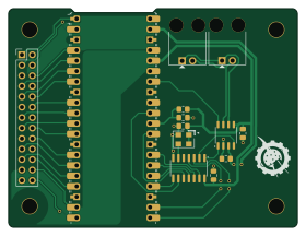
About the Pico CAN-FD Adapter PCB
Pico CAN-FD Adapter is an open source RP2040/RP2350 PCB design by RealtimeRoboticsGroup, published on GitHub under the SHL-2.1 license. It is a 2-layer board measuring 70 × 53 mm, with 13 components from 8 distinct parts.
Its main chip is the SC1631, from the RP2040/RP2350 family. Other key parts include the MCP2558FD-H/SN, ECS-5032MV-40-CN and MCP2518FDT-H/SL. By type, the board carries 5 capacitors, 3 ICs, 3 connectors, 1 module and 1 resistor.
From the project
This project is open-source hardware and is licensed under the Solderpad Hardware License v2.1 (the "License"), which is a permissive license based on the Apache License, Version 2.0.
This project is open-source hardware and is licensed under the Solderpad Hardware License v2.1 (the "License"), which is a permissive license based on the Apache License, Version 2.0.
You may use this work under the terms of the Solderpad Hardware License v2.1, or, at your option, under the terms of the Apache License, Version 2.0.
- Solderpad v2.1: Solderpad Hardware License v2.1 - Solderpad Hardware License
Main components on the Pico CAN-FD Adapter
Pico CAN-FD Adapter bill of materials (BOM)
13 components, 8 distinct parts — part numbers from the project's BOM.
| Qty | Part | Footprint | Refs |
|---|---|---|---|
| 1 | MCP2558FD-H/SN MCP2558FD | SO-8_3.9x4.9mm_P1.27mm | U1 |
| 1 | ECS-5032MV-40-CN 4.0 MHz | ECS-5032MV | U2 |
| 1 | MCP2518FDT-H/SL | SO-14_3.9x8.65mm_P1.27mm | U3 |
| 1 | SC1631 RaspberryPi_Pico2 | RaspberryPi_Pico_Common_Unspecified | A1 |
| 1 | PRPC013DAAN-RC Expansion | PinHeader_2x13_P2.54mm_Vertical | J1 |
| 2 | 0705550036 CAN | 70555-0001 | J2, J3 |
| 5 | 311-1141-1 0.1uF-25V-10%-0805 | C_0805_2012Metric_Pad1.18x1.45mm_HandSolder | C1, C2, C3, C4, C5 |
| 1 | RC0805FR-071K5L 1.50k-1%-0805 | R_0805_2012Metric_Pad1.20x1.40mm_HandSolder | R1 |
Pico CAN-FD Adapter design files
The KiCad project lives in the RealtimeRoboticsGroup/electrical repository on GitHub; these links point at the commit this page was built from.
Pico CAN-FD Adapter: common questions
What microcontroller does the Pico CAN-FD Adapter use?
The Pico CAN-FD Adapter is built around the SC1631, from the RP2040/RP2350 family.
How big is the Pico CAN-FD Adapter PCB?
The Pico CAN-FD Adapter measures 70 × 53 mm, has 2 copper layers and is 1.6 mm thick.
How many components are on the Pico CAN-FD Adapter?
13 components, from 8 distinct parts, with part numbers taken from the project's own BOM. The full bill of materials is listed on this page.
Where can I download the Pico CAN-FD Adapter design files?
From the RealtimeRoboticsGroup/electrical repository on GitHub, which has the KiCad layout, the schematic and the BOM; the links under Design files point to each one.
Can I use the Pico CAN-FD Adapter design in my own project?
It is published under SHL-2.1, which limits how it may be reused; read the license before building on it.
Can I test firmware for the Pico CAN-FD Adapter without the hardware?
Yes. HardLabs builds a simulation of the board from its netlist and BOM, so you can run and debug RP2040/RP2350 firmware against it before you order a PCB.
More boards in electrical
 RP2040/RP2350
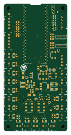
Pico Button Board
55.9 × 111.8 mm201 parts4LSHL-2.11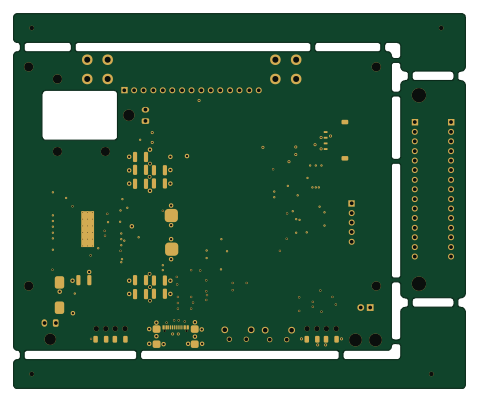 STM32
STM32NX J401 Adapter
119.6 × 99.2 mm127 parts4LSHL-2.11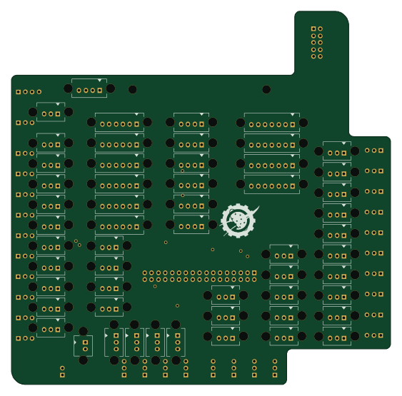
RoboRIO Interface
140.5 × 138.4 mm88 parts4LSHL-2.11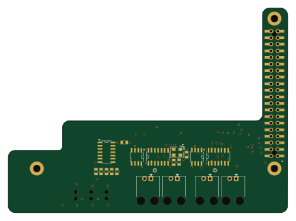
NX-IndicatorBoard V2
108.1 × 79 mm36 parts4LSHL-2.11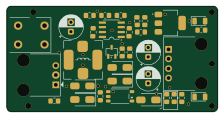 RP2040/RP2350
Beam Break Adapter
55.9 × 27.9 mm36 parts2LSHL-2.11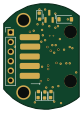
WCP Mag Encoder (WCP-2435)
19.9 × 27.8 mm22 parts4LSHL-2.11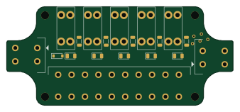
Mini Power Distribution Board (WCP-1823)
84.4 × 36.8 mm19 parts2LSHL-2.11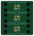
CAN Hub
29.8 × 31.5 mm6 parts2LSHL-2.11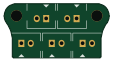
TEE CAN (WCP-1824)
27.9 × 14.5 mm5 parts2LSHL-2.11
Similar boards
 RP2040/RP2350
Open Book Abridged Edition
joeycastillo
85 × 115 mm29 parts2LCC-BY-SA-4.08.1k RP2040/RP2350
Corne
foostan
277.2 × 107.5 mm164 parts2LCC-BY-4.07.7k RP2040/RP2350
Corne
277.2 × 107.5 mm164 parts2LCC-BY-4.07.7k RP2040/RP2350
LogicAnalyzer
gusmanb
57 × 55.2 mm6 parts2LGPL-3.05.0k RP2040/RP2350
Jitx design
55.5 × 65 mm26 parts4LGPL-3.05.0k RP2040/RP2350
Pro V2
kata0510
290.1 × 130 mm270 parts2LMIT2.3k