
MCU Datalogger

About the MCU Datalogger PCB
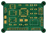
MCU Datalogger is an open source AVR/Arduino PCB design by Reon-02, published on GitHub. It is a 2-layer board measuring 48.6 × 34.3 mm, with 25 components from 16 distinct parts.
Its main chip is the ATMEGA328P-AU, from the AVR/Arduino family. Other key parts include the 24LC1025 and DS1337S. By type, the board carries 7 resistors, 5 capacitors, 4 ICs, 4 connectors, 2 crystals and 2 diodes.
From the project
A microcontroller-based data logger PCB designed using KiCad as part of the PCB Design with KiCad - Updated for KiCad 9 Udemy course.
A microcontroller-based data logger PCB designed using KiCad as part of the PCB Design with KiCad - Updated for KiCad 9 Udemy course.
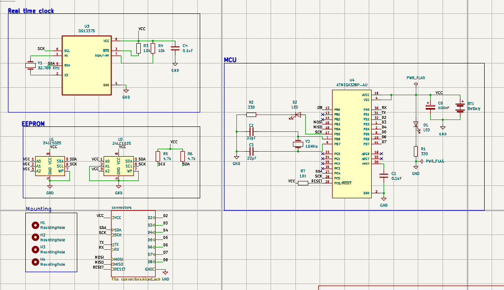
The project is built around an ATmega328P-AU microcontroller and includes an external real-time clock, EEPROM memory, communication interfaces, programming interface, and external I/O connections. Both 2-layer and 4-layer PCB versions were designed.
Main components on the MCU Datalogger
MCU Datalogger bill of materials (BOM)
25 components, 16 distinct parts.
| Qty | Part | Footprint | Refs |
|---|---|---|---|
| 2 | 24LC1025 | SOIC-8_5.3x5.3mm_P1.27mm | U1, U2 |
| 1 | DS1337S | DS1337S+ | U3 |
| 1 | ATMEGA328P-AU | ATMEGA328P-AU | U4 |
| 1 | 32.768 KHz | Crystal_SMD_5032-2Pin_5.0x3.2mm_HandSoldering | Y1 |
| 1 | 16MHz | Crystal_SMD_5032-2Pin_5.0x3.2mm_HandSoldering | Y2 |
| 2 | Conn_01x04_Pin | PinHeader_1x04_P2.54mm_Vertical | J1, J2 |
| 1 | Conn_01x09_Pin | PinHeader_1x09_P2.54mm_Vertical | J3 |
| 1 | Conn_02x03_Odd_Even | PinHeader_2x03_P2.54mm_Vertical | J4 |
| 1 | Battery | PinHeader_1x02_P2.54mm_Vertical | BT1 |
| 2 | LED | LED_0805_2012Metric | D1, D2 |
| 2 | 0.1uF | C_0805_2012Metric | C1, C4 |
| 2 | 22pF | C_0805_2012Metric | C2, C3 |
| 1 | 100nF | C_0805_2012Metric | C5 |
| 2 | 330 | R_0805_2012Metric | R1, R2 |
| 3 | 10k | R_0805_2012Metric | R3, R4, R7 |
| 2 | 4.7k | R_0805_2012Metric | R5, R6 |
MCU Datalogger design files
The KiCad project lives in the Reon-02/PCB-Design-with-KiCad-Udemy repository on GitHub; these links point at the commit this page was built from.
MCU Datalogger: common questions
What microcontroller does the MCU Datalogger use?
The MCU Datalogger is built around the ATMEGA328P-AU, from the AVR/Arduino family.
How big is the MCU Datalogger PCB?
The MCU Datalogger measures 48.6 × 34.3 mm, has 2 copper layers and is 1.6 mm thick.
How many components are on the MCU Datalogger?
25 components, from 16 distinct parts. The full bill of materials is listed on this page.
Where can I download the MCU Datalogger design files?
From the Reon-02/PCB-Design-with-KiCad-Udemy repository on GitHub, which has the KiCad layout and the schematic; the links under Design files point to each one.
Can I use the MCU Datalogger design in my own project?
The repository has no license, so all rights stay with Reon-02. Use it as a reference, and ask the author before reusing the design.
Can I test firmware for the MCU Datalogger without the hardware?
Yes. HardLabs builds a simulation of the board from its netlist and BOM, so you can run and debug AVR/Arduino firmware against it before you order a PCB.
More boards in PCB-Design-with-KiCad-Udemy
Similar boards
 AVR/Arduino
Magspoof
samyk
35 × 29 mm11 parts2LNo license4.2k AVR/Arduino
Redox keyboard
mattdibi
162.2 × 126.5 mm77 parts2LMIT2.0k AVR/Arduino
Labrador
espotek-org
36.8 × 34.7 mm75 parts2LNo license1.2k AVR/Arduino
ModuleV450
stuartpittaway
30 × 61.4 mm39 parts2LCC-BY-NC-4.01.1k AVR/Arduino
V4
30 × 50 mm38 parts2LCC-BY-NC-4.01.1k AVR/Arduino
Discipline
coseyfannitutti
304.9 × 122.8 mm170 parts2LCC-BY-NC-4.01.0k