
Sun sensor test

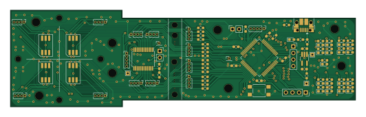
About the Sun sensor test PCB
Sun sensor test is an open source STM32 PCB design by rgw3d, published on GitHub under the GPL-3.0 license. It is a 2-layer board measuring 132.7 × 37.3 mm, with 151 components from 54 distinct parts.
Its main chip is the STM32L496ZGTX, from the STM32 family. Other key parts include the MR25H10, TPL5010, TPS270 and 74LVC1G07. By type, the board carries 93 resistors, 21 connectors, 18 diodes, 11 capacitors, 7 ICs and 1 switch.
It belongs with the sensors and science & space designs in this gallery.
From the project
Hardware design files for my $1000 CubeSat.
Testing out a potential sun sensor using the K857PE 4-Quadrent Photodiode. See the pdf for more information.
See my video on this board for more information.
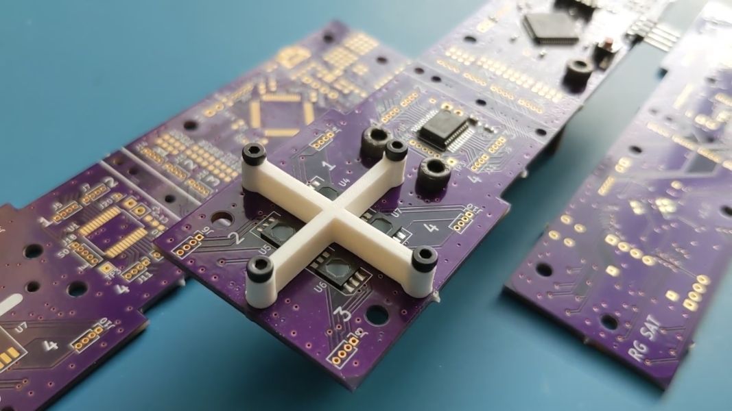
Main components on the Sun sensor test
Sun sensor test bill of materials (BOM)
151 components, 54 distinct parts — part numbers from the project's BOM.
| Qty | Part | Footprint | Refs |
|---|---|---|---|
| 1 | STM32L496ZGTX CD74HC4067SM | SSOP-24_5.3x8.2mm_P0.65mm | U1 |
| 1 | MR25H10 STM32L051R8Tx | LQFP-64_10x10mm_P0.5mm | U2 |
| 1 | TPL5010 ADP150AUJZ-3.3-R7 | TSOT-23-5_HandSoldering | U3 |
| 2 | TPS270 K857PE | K857PE | U4, U5 |
| 2 | 74LVC1G07 K857PE | K857PE | U6, U7 |
| 1 | CONN_01X04 2.54mm | PinSocket_1x04_P2.54mm_Vertical | J1 |
| 1 | CONN_01X02_FEMALE 2.54mm | PinSocket_1x04_P2.54mm_Vertical | J2 |
| 1 | CONN_01X04 USB_B_Micro | USB_Micro-B_Amphenol_10103594-0001LF_Horizontal | J3 |
| 1 | CONN_01X02_FEMALE Conn_01x04_Female | PinHeader_1x04_P1.27mm_Vertical | J4 |
| 4 | CONN_01X04 Conn_01x04_Female | PinHeader_1x04_P1.27mm_Vertical | J5, J7, J8, J9 |
| 1 | CONN_02X20_ODD_EVEN Conn_01x04_Female | PinHeader_1x04_P1.27mm_Vertical | J6 |
| 6 | Conn_01x04_Female | PinHeader_1x04_P1.27mm_Vertical | J10, J11, J14, J15, J16, J17 |
| 1 | CONN_01X05 Conn_01x02 | PinSocket_1x02_P2.54mm_Vertical | J12 |
| 1 | CONN_01X04_MALE Conn_01x02 | PinSocket_1x02_P2.54mm_Vertical | J13 |
| 2 | Conn_01x05_Female | PinHeader_1x05_P1.27mm_Vertical | J18, J19 |
| 2 | 1.27mm | PinHeader_1x01_P1.27mm_Vertical | J20, J21 |
| 1 | SW_DIP_X01 SW_Push | SW_SPST_TL3305A | SW1 |
| 5 | RED | LED_0603_1608Metric_Pad1.05x0.95mm_HandSolder | D1, D2, D3, D4, D5 |
| 4 | ESD9B5.0ST5G RED | LED_0603_1608Metric_Pad1.05x0.95mm_HandSolder | D6, D7, D8, D18 |
| 1 | NUP2105L RED | LED_0603_1608Metric_Pad1.05x0.95mm_HandSolder | D9 |
Show 34 more
| Qty | Part | Footprint | Refs |
|---|---|---|---|
| 8 | NRVB120VLSFT1G RED | LED_0603_1608Metric_Pad1.05x0.95mm_HandSolder | D10, D11, D12, D13, D14, D15, D16, D17 |
| 2 | 0.01UF 0.1uF | C_0603_1608Metric_Pad1.08x0.95mm_HandSolder | C1, C2 |
| 1 | 4.7UF 0.1uF | C_0603_1608Metric_Pad1.08x0.95mm_HandSolder | C3 |
| 4 | 0.1UF 0.1uF | C_0603_1608Metric_Pad1.08x0.95mm_HandSolder | C4, C5, C6, C7 |
| 2 | 0.1UF 1uF | C_0603_1608Metric_Pad1.08x0.95mm_HandSolder | C8, C9 |
| 2 | 0.1UF 4.7uF | C_0603_1608Metric_Pad1.08x0.95mm_HandSolder | C10, C11 |
| 9 | DNP | R_0603_1608Metric_Pad0.98x0.95mm_HandSolder | R1, R63, R75, R87, R88, R89, R90, R91 +1 |
| 6 | 10M DNP | R_0603_1608Metric_Pad0.98x0.95mm_HandSolder | R2, R3, R4, R7, R49, R53 |
| 1 | 100K 10K | R_0603_1608Metric_Pad0.98x0.95mm_HandSolder | R5 |
| 14 | 100K DNP | R_0603_1608Metric_Pad0.98x0.95mm_HandSolder | R6, R8, R12, R13, R14, R46, R47, R50 +6 |
| 1 | 224K DNP | R_0603_1608Metric_Pad0.98x0.95mm_HandSolder | R9 |
| 1 | 100K | R_0603_1608Metric_Pad0.98x0.95mm_HandSolder | R10 |
| 1 | 10K | R_0603_1608Metric_Pad0.98x0.95mm_HandSolder | R11 |
| 1 | 8.85K DNP | R_0603_1608Metric_Pad0.98x0.95mm_HandSolder | R15 |
| 5 | 100K 680 | R_0603_1608Metric_Pad0.98x0.95mm_HandSolder | R16, R17, R18, R32, R33 |
| 4 | 49.9 DNP | R_0603_1608Metric_Pad0.98x0.95mm_HandSolder | R19, R20, R21, R22 |
| 1 | 49.9 680 | R_0603_1608Metric_Pad0.98x0.95mm_HandSolder | R23 |
| 5 | 330 680 | R_0603_1608Metric_Pad0.98x0.95mm_HandSolder | R24, R25, R26, R27, R28 |
| 6 | 680 | R_0603_1608Metric_Pad0.98x0.95mm_HandSolder | R29, R30, R31, R36, R37, R38 |
| 2 | 150K 0 | R_0603_1608Metric_Pad0.98x0.95mm_HandSolder | R34, R43 |
| 1 | 330 | R_0603_1608Metric_Pad0.98x0.95mm_HandSolder | R35 |
| 1 | 60.4 0 | R_0603_1608Metric_Pad0.98x0.95mm_HandSolder | R39 |
| 1 | 60.4 DNP | R_0603_1608Metric_Pad0.98x0.95mm_HandSolder | R40 |
| 4 | 100K 0 | R_0603_1608Metric_Pad0.98x0.95mm_HandSolder | R41, R42, R68, R80 |
| 8 | 0 | R_0603_1608Metric_Pad0.98x0.95mm_HandSolder | R44, R45, R57, R58, R70, R71, R82, R83 |
| 8 | 10K DNP | R_0603_1608Metric_Pad0.98x0.95mm_HandSolder | R48, R62, R64, R66, R74, R76, R78, R79 |
| 3 | 10M 0 | R_0603_1608Metric_Pad0.98x0.95mm_HandSolder | R54, R55, R56 |
| 2 | 26.7K DNP | R_0603_1608Metric_Pad0.98x0.95mm_HandSolder | R61, R73 |
| 1 | 10K 0 | R_0603_1608Metric_Pad0.98x0.95mm_HandSolder | R67 |
| 2 | 280K 0 | R_0603_1608Metric_Pad0.98x0.95mm_HandSolder | R69, R81 |
| 1 | 3.09K DNP | R_0603_1608Metric_Pad0.98x0.95mm_HandSolder | R72 |
| 1 | 3.09K 0 | R_0603_1608Metric_Pad0.98x0.95mm_HandSolder | R84 |
| 2 | 150 DNP | R_0603_1608Metric_Pad0.98x0.95mm_HandSolder | R85, R86 |
| 1 | 0.1 0 | R_0603_1608Metric_Pad0.98x0.95mm_HandSolder | R93 |
Sun sensor test design files
The KiCad project lives in the rgw3d/1KCubeSat_Hardware repository on GitHub; these links point at the commit this page was built from.
Sun sensor test: common questions
What microcontroller does the Sun sensor test use?
The Sun sensor test is built around the STM32L496ZGTX, from the STM32 family.
How big is the Sun sensor test PCB?
The Sun sensor test measures 132.7 × 37.3 mm, has 2 copper layers and is 1.6 mm thick.
How many components are on the Sun sensor test?
151 components, from 54 distinct parts, with part numbers taken from the project's own BOM. The full bill of materials is listed on this page.
Where can I download the Sun sensor test design files?
From the rgw3d/1KCubeSat_Hardware repository on GitHub, which has the KiCad layout and the BOM; the links under Design files point to each one.
Can I use the Sun sensor test design in my own project?
Yes, under the terms of its GPL-3.0 license, which rgw3d chose for the repository.
Can I test firmware for the Sun sensor test without the hardware?
Yes. HardLabs builds a simulation of the board from its netlist and BOM, so you can run and debug STM32 firmware against it before you order a PCB.
More boards in 1KCubeSat_Hardware
Similar boards
 STM32
LumenPnP Motherboard
opulo-inc
149 × 95 mm296 parts4LCC-BY-SA-4.03.7k STM32
Type g
google
169 × 30 mm24 parts2LApache-2.02.9k STM32
Base
52.3 × 52.3 mm36 parts2LApache-2.02.9k STM32
Main panel
234 × 84 mm26 parts4LApache-2.02.9k STM32
Type a
150 × 30 mm14 parts2LApache-2.02.9k STM32
Type c
188 × 30 mm17 parts2LApache-2.02.9k