
PickOMatic-V2

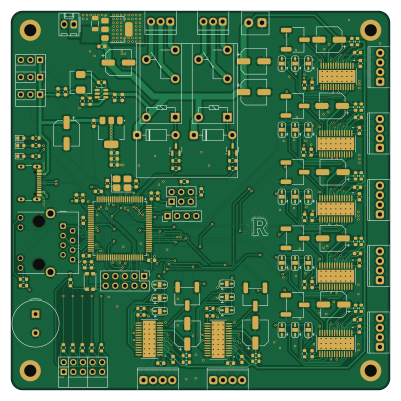
About the PickOMatic-V2 PCB
PickOMatic-V2 is an open source RISC-V PCB design by rmingon, published on GitHub under the CERN-OHL-S-2.0 license. It is a 4-layer board measuring 100 × 100 mm, with 146 components from 45 distinct parts.
Its main chip is the LQFP-100_14x14mm_P0.5mm, from the RISC-V family. Other key parts include the DRV8825PWPR, TPS562200, LM317_SOT-223 and SSP1117-3.3V. By type, the board carries 54 capacitors, 41 resistors, 20 connectors, 11 ICs, 5 diodes and 2 transistors.
It belongs with the robotics & motion and usb & debug tools designs in this gallery.
From the project
One board to drive your entire pick-and-place machine: RISC-V CH32V317, 7 stepper channels, Ethernet, USB-C, vacuum and lighting control. Open hardware.
PickOMatic V2 is a professional-grade, all-in-one motion control board designed from the ground up for desktop pick-and-place machines. It is the second generation of the PickOMatic motion controller, rebuilt around a modern 32-bit RISC-V microcontroller with native Ethernet and USB-C connectivity.
One board drives the entire machine: gantry, picker heads, nozzles, vacuum, lighting and feedback, with no shields, no breakout spaghetti and no compromises.
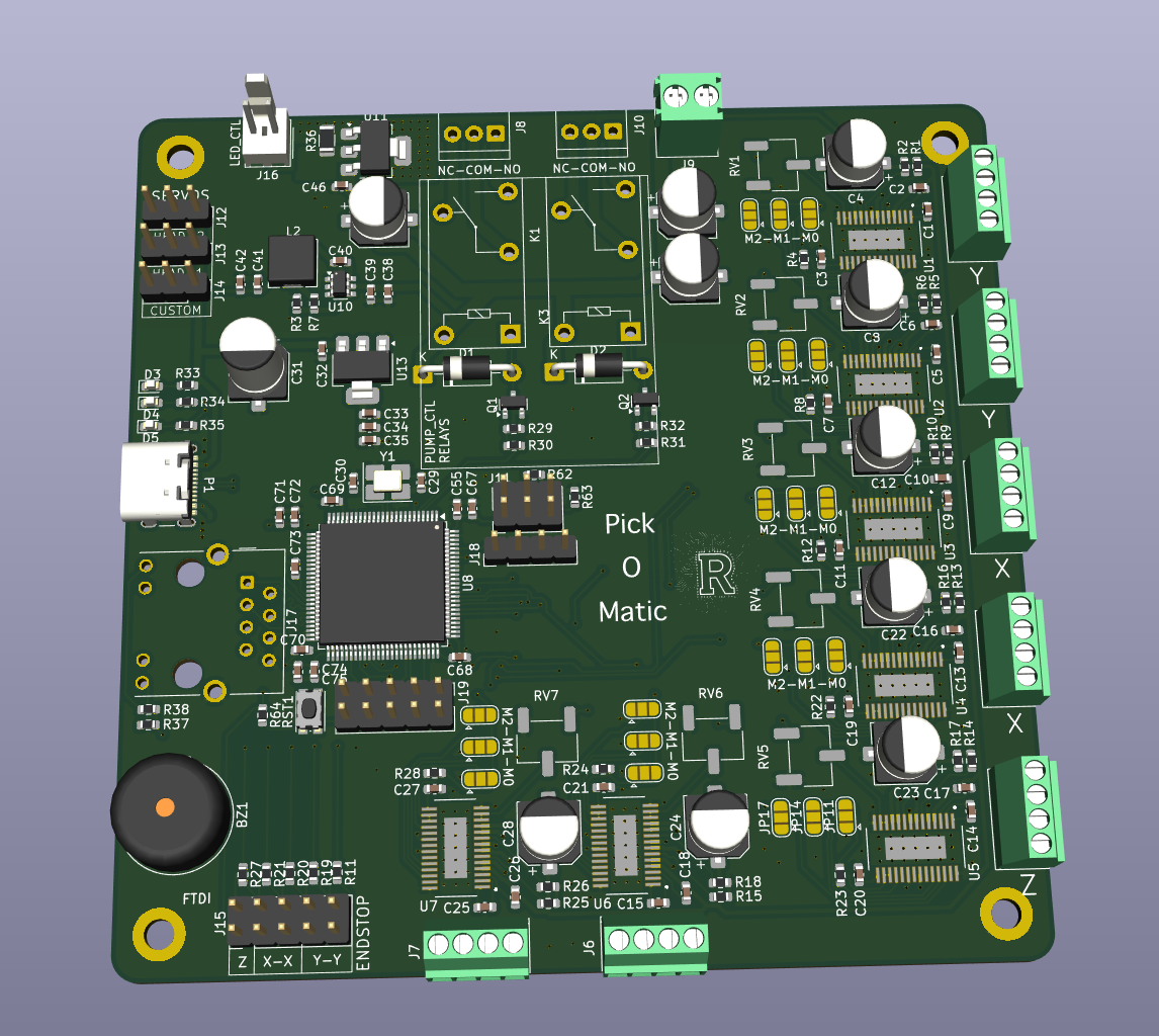
Main components on the PickOMatic-V2
PickOMatic-V2 bill of materials (BOM)
146 components, 45 distinct parts.
| Qty | Part | Footprint | Refs |
|---|---|---|---|
| 7 | DRV8825PWPR | IC_TPS61196PWPRQ1 | U1, U2, U3, U4, U5, U6, U7 |
| 1 | ~ | LQFP-100_14x14mm_P0.5mm | U8 |
| 1 | TPS562200 | SOT-23-6 | U10 |
| 1 | LM317_SOT-223 | SOT-223-3_TabPin2 | U11 |
| 1 | SSP1117-3.3V | SOT-223-3_TabPin2 | U13 |
| 2 | AO3400A | SOT-23 | Q1, Q2 |
| 1 | Crystal_GND24 | Crystal_SMD_3225-4Pin_3.2x2.5mm_HandSoldering | Y1 |
| 7 | Conn_01x04_Pin | TerminalBlock_Phoenix_MPT-0,5-4-2.54_1x04_P2.54mm_Horizontal | J1, J2, J3, J4, J5, J6, J7 |
| 2 | Conn_01x03 | TerminalBlock_TE_282834-3_1x03_P2.54mm_Horizontal | J8, J10 |
| 1 | Conn_01x02 | TerminalBlock_Phoenix_PT-1,5-2-3.5-H_1x02_P3.50mm_Horizontal | J9 |
| 1 | Conn_02x03_Odd_Even | PinHeader_2x03_P2.54mm_Vertical | J11 |
| 3 | Conn_01x03 | PinHeader_1x03_P2.54mm_Vertical | J12, J13, J14 |
| 2 | Conn_02x05_Odd_Even | PinHeader_2x05_P2.54mm_Vertical | J15, J19 |
| 1 | Conn_01x02 | Molex_KK-254_AE-6410-02A_1x02_P2.54mm_Vertical | J16 |
| 1 | RJ45_Hanrun_HR911105A_Horizontal | RJ45_Hanrun_HR911105A_Horizontal | J17 |
| 1 | Conn_01x04 | PinHeader_1x04_P2.54mm_Vertical | J18 |
| 1 | USB_C_Plug | USB_C_Receptacle_GCT_USB4105-xx-A_16P_TopMnt_Horizontal | P1 |
| 1 | Buzzer | Buzzer_TDK_PS1240P02BT_D12.2mm_H6.5mm | BZ1 |
| 2 | G5Q-1 | Relay_SPDT_Omron-G5Q-1 | K1, K3 |
| 1 | SW_DPST_x2 | SW_Push_1P1T_NO_CK_KMR2 | RST1 |
Show 25 more
| Qty | Part | Footprint | Refs |
|---|---|---|---|
| 7 | 10k | Potentiometer_Bourns_3269W_Vertical | RV1, RV2, RV3, RV4, RV5, RV6, RV7 |
| 2 | 1N4001 | D_DO-41_SOD81_P10.16mm_Horizontal | D1, D2 |
| 3 | LED | LED_0603_1608Metric | D3, D4, D5 |
| 1 | 4.7uH | L_Chilisin_BMRA00050520 | L2 |
| 7 | 10n | C_0603_1608Metric | C1, C5, C9, C13, C14, C15, C25 |
| 7 | 0.1u | C_0603_1608Metric | C2, C6, C10, C16, C17, C18, C26 |
| 7 | 0.47u | C_0603_1608Metric | C3, C7, C11, C19, C20, C21, C27 |
| 10 | 100n | CP_Elec_6.3x5.7 | C4, C8, C12, C22, C23, C24, C28, C43 +2 |
| 4 | 10pf | C_0603_1608Metric | C29, C30, C46, C55 |
| 1 | 47uF | CP_Elec_6.3x9.9 | C31 |
| 3 | 3.3uf | C_0603_1608Metric | C32, C33, C35 |
| 1 | 0.1uF | C_0603_1608Metric | C34 |
| 2 | 10u | C_0603_1608Metric | C38, C39 |
| 1 | 0.1µF | C_0603_1608Metric | C40 |
| 2 | 22u | C_0603_1608Metric | C41, C42 |
| 7 | 100nF | C_0603_1608Metric | C67, C68, C69, C70, C71, C74, C75 |
| 2 | 1µf | C_0603_1608Metric | C72, C73 |
| 14 | 0.10 | R_0603_1608Metric | R1, R2, R5, R6, R9, R10, R13, R14 +6 |
| 17 | 10K | R_0603_1608Metric | R3, R4, R8, R11, R12, R19, R20, R21 +9 |
| 1 | 33.0K | R_0603_1608Metric | R7 |
| 2 | 680 | R_0603_1608Metric | R30, R31 |
| 1 | 500 | R_0603_1608Metric | R33 |
| 2 | 1.1K | R_0603_1608Metric | R34, R35 |
| 1 | 12 | R_1206_3216Metric | R36 |
| 3 | R_Small | R_0603_1608Metric | R37, R38, R64 |
PickOMatic-V2 design files
The KiCad project lives in the rmingon/PickOMatic-V2 repository on GitHub; these links point at the commit this page was built from.
- Layouthardware/hardware.kicad_pcb
- Schematichardware/hardware.kicad_sch
PickOMatic-V2: common questions
What microcontroller does the PickOMatic-V2 use?
The PickOMatic-V2 is built around the LQFP-100_14x14mm_P0.5mm, from the RISC-V family.
How big is the PickOMatic-V2 PCB?
The PickOMatic-V2 measures 100 × 100 mm, has 4 copper layers and is 1.6 mm thick.
How many components are on the PickOMatic-V2?
146 components, from 45 distinct parts. The full bill of materials is listed on this page.
Where can I download the PickOMatic-V2 design files?
From the rmingon/PickOMatic-V2 repository on GitHub, which has the KiCad layout and the schematic; the links under Design files point to each one.
Can I use the PickOMatic-V2 design in my own project?
Yes, under the terms of its CERN-OHL-S-2.0 license, which rmingon chose for the repository.
Can I test firmware for the PickOMatic-V2 without the hardware?
Yes. HardLabs builds a simulation of the board from its netlist and BOM, so you can run and debug RISC-V firmware against it before you order a PCB.
Similar boards
 RISC-V
Workbench-1 Controller
Quchaosheng
160 × 130 mm106 parts8LApache-2.0129 RISC-V
Keytartouch
cnlohr
152.5 × 117.5 mm69 parts2LMIT105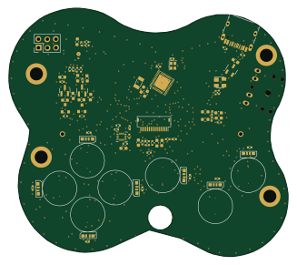 RISC-V
Froggyswadge
81.5 × 72.2 mm92 parts2LMIT105 RISC-V
Ch32v003f4u6 with wsled
40.6 × 44.5 mm26 parts2LMIT105 RISC-V
NorthPoleCircuit
Janky-Jingle-Crew
150 × 110 mm46 parts4LNo license62 RISC-V
Osc sg90-v006
OpenServoCore
20.6 × 9.6 mm26 parts4LApache-2.034