
RamRomBoard

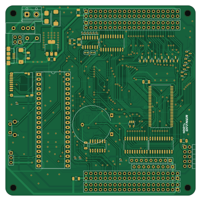
About the RamRomBoard PCB
RamRomBoard is an open source STM32 PCB design by roberto314, published on GitHub under the BSD-2-Clause license. It is a 2-layer board measuring 100 × 100 mm, with 86 components from 37 distinct parts.
Its main chip is the STM32F401, from the STM32 family. Other key parts include the 74LVC125, AZ1117-3.3, 74LVC08AD, DS1085 and 74LVC1G32. By type, the board carries 20 ICs, 16 capacitors, 14 test points, 12 resistors, 11 diodes and 9 connectors.
It belongs with the retro computing and usb & debug tools designs in this gallery.
From the project
A modular 8-bit Computer able to recreate (nearly) every Retro computer of the late 70s to mid 80s.
A modular 8-bit Computer able to recreate (nearly) every microcomputer of the mid 70s to early 80s in Hardware without FPGAs (although an FPGA can be added). Can also be used as a teaching tool for:
VHDL or Verilog C RTOS (STM32F401 runs ChibiOS. Link: https://www.chibios.org) Python bash and linux in general (Olimex board runs linux with fbterm and tmux) Harwaredesign Timing of CPUs maybe Assembler SPI and I2C Interfaces CPLDs and FPGAs
Main components on the RamRomBoard
RamRomBoard bill of materials (BOM)
86 components, 37 distinct parts.
| Qty | Part | Footprint | Refs |
|---|---|---|---|
| 1 | 74LVC125 | SOIC-14_3.9x8.7mm_P1.27mm | U1 |
| 1 | AZ1117-3.3 | SOT-223-3_TabPin2 | U2 |
| 1 | 74LVC08AD | SOIC-14_3.9x8.7mm_P1.27mm | U3 |
| 1 | DS1085 | SOIC-8_3.9x4.9mm_P1.27mm | U4 |
| 1 | 74LVC1G32 | SOT-23-5_HandSoldering | U5 |
| 2 | 74AHC1G14 | SOT-23-5 | U6, U10 |
| 3 | 74HC590 | SOIC-16_3.9x9.9mm_P1.27mm | U7, U8, U9 |
| 1 | IS61WV102416FBLL1T2 | TSOP-II-54_22.2x10.16mm_P0.8mm | U11 |
| 1 | IS61WV10248EDBLL-10TL | TSOP-II-44_10.16x18.41mm_P0.8mm | U12 |
| 3 | 74LVC595 | SO-16_3.9x9.9mm_P1.27mm | U13, U14, U17 |
| 3 | SN74LVC245ANSR | SO-20_5.3x12.6mm_P1.27mm | U15, U16, U19 |
| 1 | 74HC165 | SOIC-16_3.9x9.9mm_P1.27mm | U18 |
| 1 | DS1314 | SOIC-8_3.9x4.9mm_P1.27mm | U20 |
| 2 | BUS | PinSocket_2x20_P2.54mm_Vertical | J1, J2 |
| 1 | VSEL | PinHeader_1x03_P2.54mm_Vertical | J3 |
| 1 | Screw_Terminal_01x02 | TerminalBlock_RND_205-00012_1x02_P5.00mm_Horizontal | J5 |
| 1 | USB_B_Micro | USB_Micro-B_Amphenol_10104110_Horizontal | J6 |
| 1 | STM32F401 | DIP-40_W15.24mm_Socket_LongPads | J7 |
| 1 | Dual LED Socket | PinHeader_2x02_P2.54mm_Vertical | J8 |
| 1 | JTAG | PinHeader_2x05_P2.54mm_Horizontal | J9 |
Show 17 more
| Qty | Part | Footprint | Refs |
|---|---|---|---|
| 1 | Micro_SD_Card_Det2 | microSD_HC_Hirose_DM3D-SF | J10 |
| 1 | CR2032 | Battery_CR2032_Horizontal_ThreeHoles | BT1 |
| 1 | Polyfuse | Fuse_Littelfuse_395Series | F1 |
| 1 | 033TBVSA | ToggleSwitch_CTS_033TBVS | SW1 |
| 1 | SW_Push | SW_Tactile_SPST_Angled_PTS645Vx31-2LFS | SW2 |
| 2 | Spare | PinSocket_2x20_P2.54mm_Vertical | TP1, TP2 |
| 9 | . | PinHeader_1x01_P1.00mm_Vertical | TP3, TP4, TP5, TP6, TP8, TP9, TP12, TP13 +1 |
| 1 | CPR | PinHeader_1x01_P1.00mm_Vertical | TP7 |
| 1 | ~{BW} | PinHeader_1x01_P1.00mm_Vertical | TP10 |
| 1 | ~{CEin} | PinHeader_1x01_P1.00mm_Vertical | TP11 |
| 1 | UM1S | D_SMB | D1 |
| 10 | BAV70 | SOT-23 | D2, D3, D4, D5, D6, D7, D8, D9 +2 |
| 13 | 100n | C_1206_3216Metric | C1, C2, C3, C5, C6, C7, C8, C9 +5 |
| 3 | 33u/16 | CP_EIA-7343-31_Kemet-D | C4, C12, C15 |
| 6 | 1k | R_1206_3216Metric | R1, R2, R3, R4, R7, R8 |
| 4 | 10k | R_1206_3216Metric | R5, R6, R9, R10 |
| 2 | 1k | R_Array_SIP9 | RN3, RN4 |
RamRomBoard design files
The KiCad project lives in the roberto314/Unicomp3 repository on GitHub; these links point at the commit this page was built from.
RamRomBoard: common questions
What microcontroller does the RamRomBoard use?
The RamRomBoard is built around the STM32F401, from the STM32 family.
How big is the RamRomBoard PCB?
The RamRomBoard measures 100 × 100 mm, has 2 copper layers and is 1.6 mm thick.
How many components are on the RamRomBoard?
86 components, from 37 distinct parts. The full bill of materials is listed on this page.
Where can I download the RamRomBoard design files?
From the roberto314/Unicomp3 repository on GitHub, which has the KiCad layout and the schematic; the links under Design files point to each one.
Can I use the RamRomBoard design in my own project?
Yes, under the terms of its BSD-2-Clause license, which roberto314 chose for the repository.
Can I test firmware for the RamRomBoard without the hardware?
Yes. HardLabs builds a simulation of the board from its netlist and BOM, so you can run and debug STM32 firmware against it before you order a PCB.
More boards in Unicomp3
 STM32
STM32Schematics v11
100 × 100 mm89 parts2LBSD-2-Clause0
MMU v1
100 × 100 mm79 parts2LBSD-2-Clause0
WD1771 Board
100 × 100 mm78 parts2LBSD-2-Clause0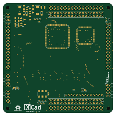
VideoBoard v1
100 × 100 mm77 parts2LBSD-2-Clause0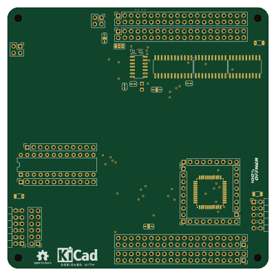
Cpu template with buffer
100 × 100 mm49 parts2LBSD-2-Clause0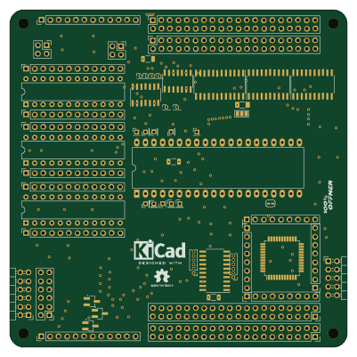
6809 CPU
100 × 100 mm39 parts2LBSD-2-Clause0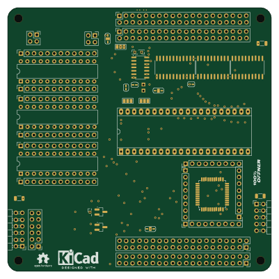
6502 6800 CPU
100 × 100 mm39 parts2LBSD-2-Clause0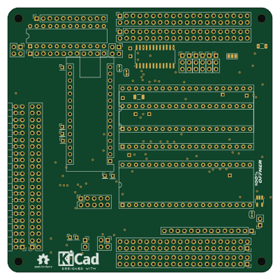 AVR/Arduino
MP Board
100 × 100 mm34 parts2LBSD-2-Clause0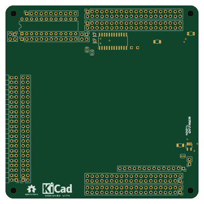
Template with buffer
100 × 100 mm31 parts2LBSD-2-Clause0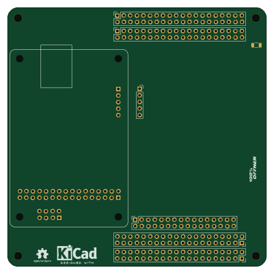
USB-Serial InputBoard
100 × 100 mm10 parts2LBSD-2-Clause0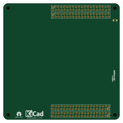
EmptyBoard
100 × 100 mm7 parts2LBSD-2-Clause0
Similar boards
 STM32
STM32LumenPnP Motherboard
opulo-inc
149 × 95 mm296 parts4LCC-BY-SA-4.03.7k STM32
STM32Type c
google
188 × 30 mm17 parts2LApache-2.02.9k STM32
STM32Main panel
234 × 84 mm26 parts4LApache-2.02.9k STM32
STM32Base
52.3 × 52.3 mm36 parts2LApache-2.02.9k STM32
STM32Type a
150 × 30 mm14 parts2LApache-2.02.9k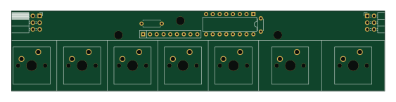 STM32
STM32Type e
140.5 × 30 mm13 parts2LApache-2.02.9k