
Clock module

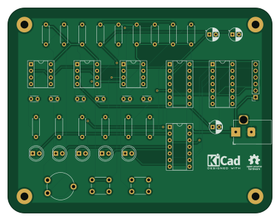
About the Clock module
Clock module is an open source PCB design by rprouse, published on GitHub under the MIT license. It is a 2-layer board measuring 101.6 × 78.7 mm, with 40 components from 22 distinct parts.
Other key parts include the NE555, 74LS04, 74LS32 and 74LS08. By type, the board carries 15 resistors, 9 capacitors, 6 ICs, 5 diodes, 2 connectors and 2 switches.
It belongs with the dev boards & breakouts and retro computing designs in this gallery.
From the project
Assembly code for my 8-bit 65C02 based breadboard computer
This documentation provides all the information regarding my variant of BE6502 computer:
- Differences between the builds - Getting started with the PCB.
This section describes details of each deviation from original BE6502 design.
More of a cosmetic thing, but I liked the idea of computer running automatic reset on power-up. The added appeal was that the circuitry is actually copied from the original C64, which makes it instantly 1000x cooler :) You can read more on that here: Dirk Grappendorf's 6502 project - RESET
Main components on the Clock module
Clock module bill of materials (BOM)
40 components, 22 distinct parts.
| Qty | Part | Footprint | Refs |
|---|---|---|---|
| 3 | NE555 | DIP-8_W7.62mm_Socket | U1, U2, U3 |
| 1 | 74LS04 | DIP-14_W7.62mm_Socket | U4 |
| 1 | 74LS32 | DIP-14_W7.62mm_Socket | U5 |
| 1 | 74LS08 | DIP-14_W7.62mm_Socket | U6 |
| 1 | Conn_01x06_Female | PinSocket_1x06_P2.54mm_Vertical | J1 |
| 1 | Power Input | BarrelJack_Horizontal | J2 |
| 1 | 1M | Potentiometer_Piher_PT-10-V10_Vertical | RV1 |
| 1 | Mode | SW_PUSH_6mm | SW1 |
| 1 | Step | SW_PUSH_6mm | SW2 |
| 1 | YELLOW_A | LED_D5.0mm | D1 |
| 1 | RED | LED_D5.0mm | D2 |
| 1 | GREEN | LED_D5.0mm | D3 |
| 1 | YELLOW_M | LED_D5.0mm | D4 |
| 1 | BLUE | LED_D5.0mm | D5 |
| 3 | 1uF | CP_Radial_D5.0mm_P2.50mm | C1, C2, C9 |
| 1 | 0.01uF | C_Disc_D3.0mm_W2.0mm_P2.50mm | C3 |
| 5 | 0.1uF | C_Disc_D3.0mm_W2.0mm_P2.50mm | C4, C5, C6, C7, C8 |
| 6 | 1K | R_Axial_DIN0207_L6.3mm_D2.5mm_P7.62mm_Horizontal | R1, R2, R3, R6, R8, R15 |
| 1 | 100K | R_Axial_DIN0207_L6.3mm_D2.5mm_P7.62mm_Horizontal | R4 |
| 2 | 10K | R_Axial_DIN0207_L6.3mm_D2.5mm_P7.62mm_Horizontal | R5, R7 |
Show 2 more
| Qty | Part | Footprint | Refs |
|---|---|---|---|
| 1 | 1M | R_Axial_DIN0207_L6.3mm_D2.5mm_P7.62mm_Horizontal | R9 |
| 5 | 220 | R_Axial_DIN0207_L6.3mm_D2.5mm_P7.62mm_Horizontal | R10, R11, R12, R13, R14 |
Clock module design files
The KiCad project lives in the rprouse/65C02_SBC repository on GitHub; these links point at the commit this page was built from.
Clock module: common questions
How big is the Clock module?
The Clock module measures 101.6 × 78.7 mm, has 2 copper layers and is 1.6 mm thick.
How many components are on the Clock module?
40 components, from 22 distinct parts. The full bill of materials is listed on this page.
Where can I download the Clock module design files?
From the rprouse/65C02_SBC repository on GitHub, which has the KiCad layout; the links under Design files point to each one.
Can I use the Clock module design in my own project?
Yes, under the terms of its MIT license, which rprouse chose for the repository.
More boards in 65C02_SBC
Similar boards

Breakout 112pin Connector
rusefi
174 × 58 mm39 parts2LGPL-3.01.2k
134pin 7-967288-1
139.7 × 73.7 mm38 parts2LGPL-3.01.2k
Eecv breakout
140.8 × 53.7 mm9 parts4LGPL-3.01.2k
Breakout 60pin EEC-IV
139.7 × 62.2 mm15 parts2LGPL-3.01.2k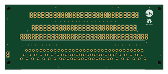
88 Pin Vag Breakout
142 × 58 mm91 parts2LGPL-3.01.2k
Expansion Card Retrofit
FrameworkComputer
24 × 27.3 mm5 parts2LCC-BY-4.01.1k