
Sensor to-CAN

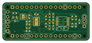
About the Sensor to-CAN PCB
Sensor to-CAN is an open source PCB design by Sarbf1, published on GitHub under the Custom license license. It is a 4-layer board measuring 46 × 20 mm, with 45 components from 19 distinct parts.
Other key parts include the NCS20074DTB, MCP2518FD-xQBB, MCP2542FDxMF and SHT4x. By type, the board carries 16 resistors, 10 capacitors, 6 connectors, 6 diodes, 4 ICs and 2 switches.
It belongs with the dev boards & breakouts and sensors designs in this gallery.
From the project
A HAT for Arduino nano, to Connect nearly any sensor and send its walues using CAN or NMEA bus
This is an early version. The hardware is drwan, but not checked or tested. The four layer board is slightly larger than the arduino nano R4, as i have added a shield ring (in case of use in high EMV areas such as in electric vehicles).
Also the code has not been written yet, but will follow.
The goal is to have a HAT board for on a Arduino Nano R4, that can connect to any sensor (3.3V 500mA, 5V 1A or Vin). The sensor vaule (any voltage, or current input, selectable with a jumper) is processed by the arduino R4 and the sent using CANbus, using NMEA2000 protocol. It has three LEDs that can…
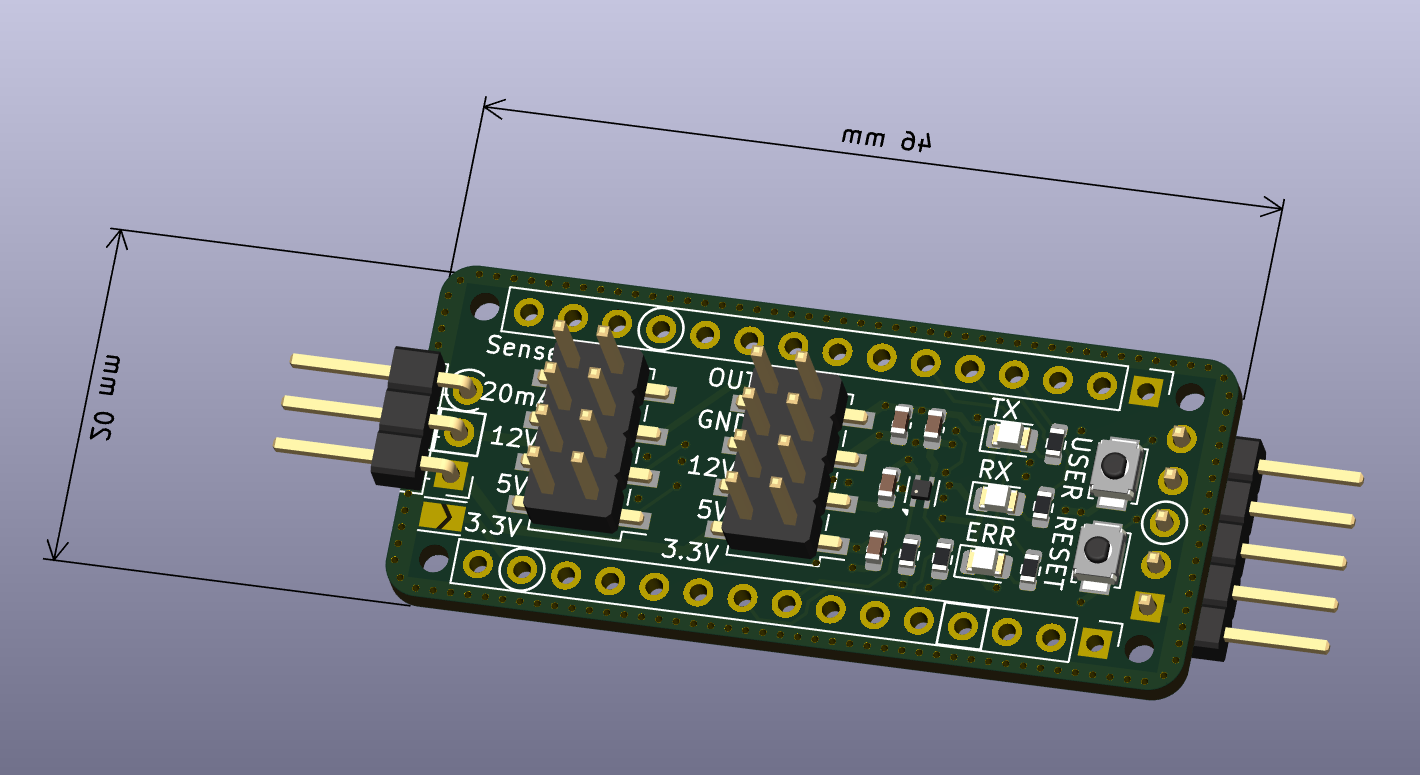
Main components on the Sensor to-CAN
Sensor to-CAN bill of materials (BOM)
45 components, 19 distinct parts.
| Qty | Part | Footprint | Refs |
|---|---|---|---|
| 1 | NCS20074DTB | TSSOP-14_4.4x5mm_P0.65mm | U1 |
| 1 | MCP2518FD-xQBB | DFN-14-1EP_3x4.5mm_P0.65mm_EP1.65x4.25mm | U2 |
| 1 | MCP2542FDxMF | DFN-8-1EP_3x3mm_P0.65mm_EP1.55x2.4mm | U3 |
| 1 | SHT4x | Sensirion_DFN-4_1.5x1.5mm_P0.8mm_SHT4x_NoCentralPad | U4 |
| 1 | ECS-200-8-33 | Oscillator_SMD_ECS_2520MV-xxx-xx-4Pin_2.5x2.0mm | Y2 |
| 1 | Analog | PinHeader_1x15_P2.54mm_Vertical | J1 |
| 1 | Digital | PinHeader_1x15_P2.54mm_Vertical | J2 |
| 2 | Conn_02x04_Counter_Clockwise | PinHeader_2x04_P2.54mm_Vertical_SMD | J3, J4 |
| 1 | Conn_01x05 | PinHeader_1x05_P2.54mm_Horizontal | J5 |
| 1 | Conn_01x03 | PinHeader_1x03_P2.54mm_Horizontal | J6 |
| 2 | SW_Push | SW_SPST_B3U-1000P | SW1, SW2 |
| 3 | LED | LED_0805_2012Metric | D1, D2, D3 |
| 1 | NUP2105L | SOT-23 | D4 |
| 2 | D_Zener_5.1V | D_SOD-323 | D5, D6 |
| 8 | 100nC | C_0603_1608Metric | C2, C3, C4, C5, C6, C7, C10, C11 |
| 2 | 8pC | C_0603_1608Metric | C8, C9 |
| 12 | 1kR | R_0603_1608Metric | R1, R2, R3, R4, R8, R9, R10, R11 +4 |
| 3 | 2kR | R_0603_1608Metric | R5, R7, R12 |
| 1 | 250R | R_0603_1608Metric | R17 |
Sensor to-CAN design files
The KiCad project lives in the Sarbf1/Sensor-to-CAN repository on GitHub; these links point at the commit this page was built from.
Sensor to-CAN: common questions
How big is the Sensor to-CAN PCB?
The Sensor to-CAN measures 46 × 20 mm, has 4 copper layers and is 1.6 mm thick.
How many components are on the Sensor to-CAN?
45 components, from 19 distinct parts. The full bill of materials is listed on this page.
Where can I download the Sensor to-CAN design files?
From the Sarbf1/Sensor-to-CAN repository on GitHub, which has the KiCad layout and the schematic; the links under Design files point to each one.
Can I use the Sensor to-CAN design in my own project?
It is published under Custom license, which limits how it may be reused; read the license before building on it.
Similar boards

Sensor smd
scottbez1
40 × 20 mm5 parts2LApache-2.04.2k
Sensors
StuckAtPrototype
15.2 × 9 mm14 parts4LApache-2.03.8k
Microphone
Mentra-Community
5.5 × 6.1 mm6 parts2LMIT1.2k
Eecv breakout
rusefi
140.8 × 53.7 mm9 parts4LGPL-3.01.2k
134pin 7-967288-1
139.7 × 73.7 mm38 parts2LGPL-3.01.2k
Breakout 60pin EEC-IV
139.7 × 62.2 mm15 parts2LGPL-3.01.2k