
Hackducky

About the Hackducky PCB
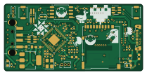
Hackducky is an open source RP2040/RP2350 PCB design by souptik-samanta, published on GitHub. It is a 4-layer board measuring 52.3 × 25.3 mm, with 61 components from 29 distinct parts.
Its main chip is the RP2040, from the RP2040/RP2350 family. Other key parts include the AMS1117-3.3, W25Q128JVS and SRV05-4. By type, the board carries 20 capacitors, 18 resistors, 6 connectors, 6 diodes, 5 ICs and 2 switches.
From the project
Our board is powered by the reliable Raspberry Pi RP2040 microcontroller and includes 16 MB of flash storage, giving plenty of room for scripts and firmware. It also features an SD card slot, allowing users to store and switch between multiple payloads or automation scripts easil
Our board is powered by the reliable Raspberry Pi RP2040 microcontroller and includes 16 MB of flash storage, giving plenty of room for scripts and firmware. It also features an SD card slot, allowing users to store and switch between multiple payloads or automation scripts easily. This makes the device flexible for experimentation, demos, and authorized security testing.
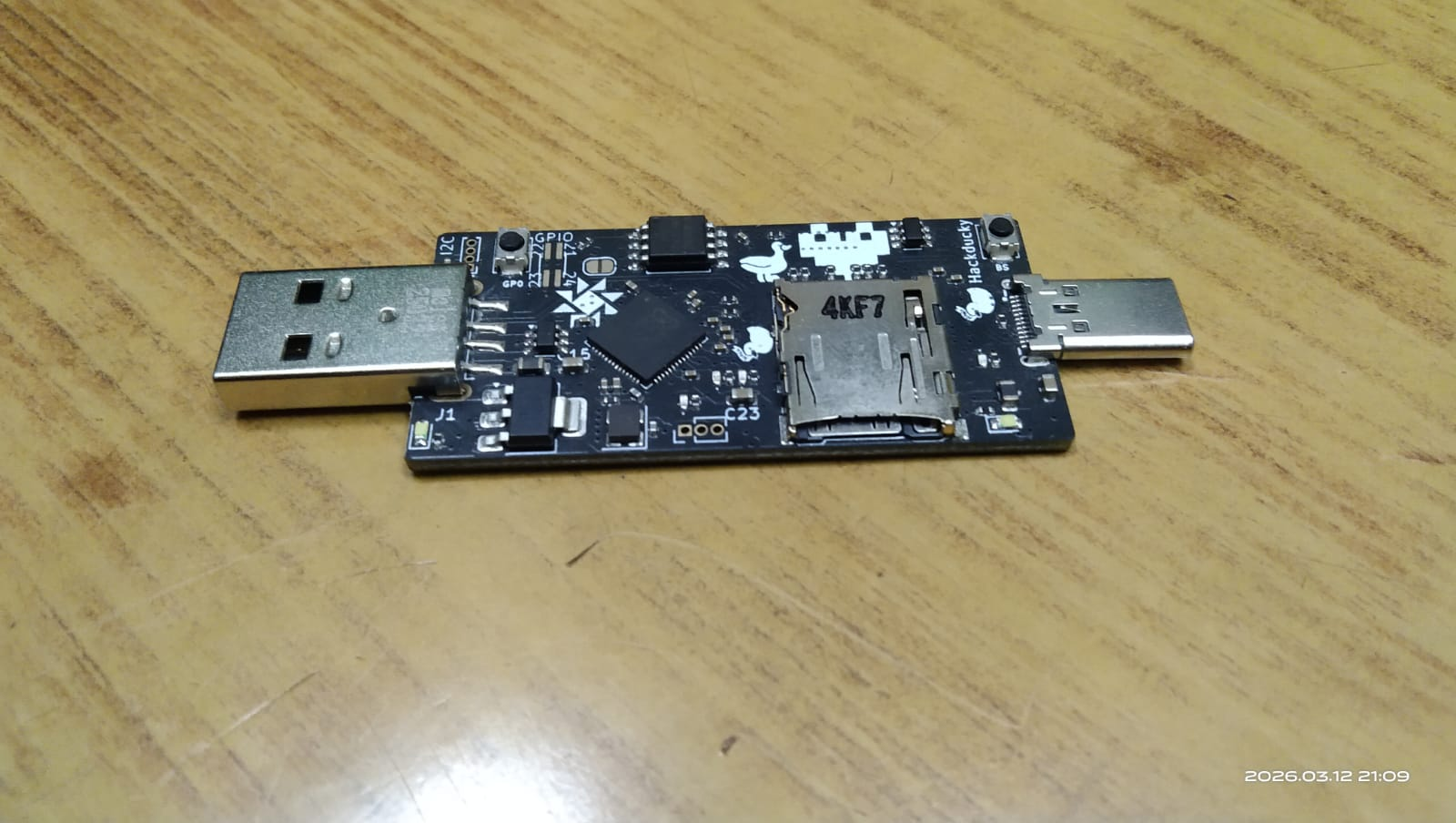
Main components on the Hackducky
Hackducky bill of materials (BOM)
61 components, 29 distinct parts — part numbers from the project's BOM.
| Qty | Part | Footprint | Refs |
|---|---|---|---|
| 1 | AMS1117-3.3 | SOT-223-3_TabPin2 | U2 |
| 1 | W25Q128JVS | SOIC-8_5.3x5.3mm_P1.27mm | U3 |
| 1 | RP2040 | QFN-56-1EP_7x7mm_P0.4mm_EP3.2x3.2mm | U4 |
| 2 | SRV05-4 | SOT-23-6 | U5, U6 |
| 1 | CRYSTAL_GND24 Crystal_GND24 | Crystal_SMD_Abracon_ABM8G-4Pin_3.2x2.5mm | Y1 |
| 1 | USB_A | USB_A_CNCTech_1001-011-01101_Horizontal | J1 |
| 1 | CONN_02X02_TOP_BOTTOM Conn_02x02_Top_Bottom | PinHeader_2x02_P1.00mm_Vertical_SMD | J2 |
| 1 | Micro_SD_Card | microSD_HC_Hirose_DM3AT-SF-PEJM5 | J3 |
| 1 | CONN_01X03_PIN Conn_01x03_Pin | PinHeader_1x03_P1.27mm_Vertical | J4 |
| 1 | CONN_01X04_PIN Conn_01x04_Pin | PinHeader_1x04_P1.00mm_Vertical | J6 |
| 1 | USB_C_Plug | USB-C-SMD_U261-121N-4BS2S | P2 |
| 1 | JUMPER_2_OPEN Jumper_2_Open | SolderJumper-2_P1.3mm_Open_RoundedPad1.0x1.5mm | JP1 |
| 1 | C318884 BOOT_SEL | SW_Push_SPST_NO_Alps_SKRK | SW3 |
| 1 | GP0 | SW_Push_SPST_NO_Alps_SKRK | SW4 |
| 4 | LED | LED_0402_1005Metric | D1, D2, D3, D4 |
| 2 | LED | LED_0603_1608Metric | D5, D6 |
| 2 | 120OHM.100MHZ 120ohm.100Mhz | L_0805_2012Metric | FB1, FB2 |
| 3 | 1UF 1uF | C_0402_1005Metric | C1, C9, C10 |
| 11 | 100NF 100nF | C_0402_1005Metric | C7, C8, C11, C17, C18, C19, C20, C21 +3 |
| 2 | 15PF 15pF | C_0402_1005Metric | C12, C13 |
Show 9 more
| Qty | Part | Footprint | Refs |
|---|---|---|---|
| 3 | 22UF 22uF | C_0603_1608Metric | C14, C15, C23 |
| 1 | 100N 100n | C_0402_1005Metric | C16 |
| 2 | R | R_0402_1005Metric | R1, R2 |
| 4 | 220 | R_0402_1005Metric | R3, R5, R6, R10 |
| 1 | 5.1K | C_0402_1005Metric | R4 |
| 2 | 27.4 | R_0402_1005Metric | R7, R22 |
| 2 | 1k | R_0402_1005Metric | R8, R9 |
| 1 | DNF | R_0402_1005Metric | R15 |
| 6 | 10K 10k | R_0402_1005Metric | R16, R17, R18, R19, R20, R21 |
Hackducky design files
The KiCad project lives in the souptik-samanta/Hackducky repository on GitHub; these links point at the commit this page was built from.
- LayoutPcb/hackducky.kicad_pcb
- SchematicPcb/hackducky.kicad_sch
- BOMproduction/bom.csv
Hackducky: common questions
What microcontroller does the Hackducky use?
The Hackducky is built around the RP2040, from the RP2040/RP2350 family.
How big is the Hackducky PCB?
The Hackducky measures 52.3 × 25.3 mm, has 4 copper layers and is 1.6 mm thick.
How many components are on the Hackducky?
61 components, from 29 distinct parts, with part numbers taken from the project's own BOM. The full bill of materials is listed on this page.
Where can I download the Hackducky design files?
From the souptik-samanta/Hackducky repository on GitHub, which has the KiCad layout, the schematic and the BOM; the links under Design files point to each one.
Can I use the Hackducky design in my own project?
The repository has no license, so all rights stay with souptik-samanta. Use it as a reference, and ask the author before reusing the design.
Can I test firmware for the Hackducky without the hardware?
Yes. HardLabs builds a simulation of the board from its netlist and BOM, so you can run and debug RP2040/RP2350 firmware against it before you order a PCB.
Similar boards
 RP2040/RP2350
Open Book Abridged Edition
joeycastillo
85 × 115 mm29 parts2LCC-BY-SA-4.08.1k RP2040/RP2350
Corne
foostan
277.2 × 107.5 mm164 parts2LCC-BY-4.07.7k RP2040/RP2350
Corne
277.2 × 107.5 mm164 parts2LCC-BY-4.07.7k RP2040/RP2350
LogicAnalyzer
gusmanb
57 × 55.2 mm6 parts2LGPL-3.05.0k RP2040/RP2350
Jitx design
55.5 × 65 mm26 parts4LGPL-3.05.0k RP2040/RP2350
Pro V2
kata0510
290.1 × 130 mm270 parts2LMIT2.3k