
Wheel Motor Driver

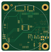
About the Wheel Motor Driver PCB
Wheel Motor Driver is an open source PCB design by SSL-A-Team, published on GitHub under the MIT license. It is a 6-layer board measuring 45 × 46 mm, with 87 components from 39 distinct parts.
Other key parts include the AS5047P and TLV70030_SOT353. By type, the board carries 40 resistors, 23 capacitors, 7 transistors, 6 diodes, 3 connectors and 3 fuses.
It belongs with the robotics & motion designs in this gallery.
From the project
circuit board design files, gerbers, and circuit analysis
All current board releases use KiCad 7.X.
See releases for competition production files. Our releases include known bug documentation, and the confirmed gerber, BoM, and CPL files sent to fab so you know you're looking and ordering what we did. Releases are accompanied by a tagged commit, for all editable project files used to generate the fab products.
For complex boards like control and kicker, we include spice models and python files that compute any relevant values from datasheets, and including documented references and links to needed formulations.
Main components on the Wheel Motor Driver
Wheel Motor Driver bill of materials (BOM)
87 components, 39 distinct parts — part numbers from the project's BOM.
| Qty | Part | Footprint | Refs |
|---|---|---|---|
| 1 | AS5047P | TSSOP-14_4.4x5mm_P0.65mm | U2 |
| 1 | TLV70030_SOT353 | SOT-353_SC-70-5 | U3 |
| 6 | STL90N10F7 | PowerFLAT_5x6 | Q1, Q2, Q3, Q4, Q5, Q6 |
| 1 | BSS138K | SOT-23 | Q7 |
| 1 | Q13FC13500005 | Crystal_SMD_3215-2Pin_3.2x1.5mm | Y1 |
| 1 | TAXM8M4RDBCCT2T | Crystal_SMD_3225-4Pin_3.2x2.5mm | Y2 |
| 1 | SM06B-SRSS-TB | JST_SH_SM06B-SRSS-TB_1x06-1MP_P1.00mm_Horizontal | J1 |
| 1 | SM06B-SRSS-TB | JST_SH_SM06B-SRSS-TB_1x06-1MP_P1.00mm_Horizontal | J3 |
| 1 | CONN_ARM_JTAG_SWD_10 Conn_ARM_JTAG_SWD_10 | Samtec-2x5pin-1.27mm | J6 |
| 1 | 06F-0200L1 | Fuse_0603_1608Metric_Pad1.05x0.95mm_HandSolder | F1 |
| 1 | 0501010.WR1 | Fuse_1206_3216Metric_Pad1.42x1.75mm_HandSolder | F2 |
| 1 | 0467.250NRHF | Fuse_0603_1608Metric_Pad1.05x0.95mm_HandSolder | F3 |
| 2 | BAS16VY | SOT-363_SC-70-6 | D1, D2 |
| 1 | XL-1608UOC-06 | LED0603 | D3 |
| 1 | XL-1608UGC-04 | LED0603 | D4 |
| 1 | XL-1608SURC-06 | LED0603 | D5 |
| 1 | SMBJ26CA | D_SMB_Non-Polar | D6 |
| 1 | C21189 650 @100MHz | R_0603_1608Metric | L1 |
| 8 | C162178 0.1uF 63V | C_0402_1005Metric | C1, C4, C6, C7, C9, C13, C14, C16 |
| 2 | C70463 1uF 63V | C_1206_3216Metric | C2, C8 |
Show 19 more
| Qty | Part | Footprint | Refs |
|---|---|---|---|
| 6 | C14445 1uF 10V | C_0402_1005Metric | C3, C5, C11, C12, C15, C17 |
| 1 | C415703 22uF 6.3V | C_0402_1005Metric | C10 |
| 2 | 15PF 15pF | C_0402_1005Metric | C18, C19 |
| 2 | 11PF 11pF | C_0402_1005Metric | C20, C21 |
| 2 | EEEFT1V101AP | CP_Elec_6.3x5.8 | C22, C23 |
| 6 | 10 | R_0402_1005Metric | R1, R4, R5, R10, R11, R14 |
| 6 | 62 | R_0402_1005Metric | R2, R3, R6, R9, R12, R13 |
| 10 | 10K 10k | R_0402_1005Metric | R7, R8, R15, R16, R28, R29, R30, R31 +2 |
| 1 | 11.5K 11.5k | R_0402_1005Metric | R17 |
| 2 | C2994646 HoLLR2512-3W-100mR-1% | 2512_CS_ADI-TypeC | R18, R27 |
| 1 | C137983 40.2k 1% | R_0402_1005Metric | R19 |
| 3 | 100K 100k | R_0402_1005Metric | R20, R34, R37 |
| 2 | C25881 2.37k 1% | R_0402_1005Metric | R22, R26 |
| 1 | C270645 140k 1% | R_0402_1005Metric | R23 |
| 1 | 10K 10.0k 1% | R_0402_1005Metric | R24 |
| 1 | C60310 60 1% | R_0402_1005Metric | R25 |
| 4 | 0 | R_0402_1005Metric | R33, R39, R41, R42 |
| 1 | 330 | R_0402_1005Metric | R35 |
| 1 | 1k | R_0402_1005Metric | R38 |
Wheel Motor Driver design files
The KiCad project lives in the SSL-A-Team/electrical repository on GitHub; these links point at the commit this page was built from.
Wheel Motor Driver: common questions
How big is the Wheel Motor Driver PCB?
The Wheel Motor Driver measures 45 × 46 mm, has 6 copper layers and is 1.5284 mm thick.
How many components are on the Wheel Motor Driver?
87 components, from 39 distinct parts, with part numbers taken from the project's own BOM. The full bill of materials is listed on this page.
Where can I download the Wheel Motor Driver design files?
From the SSL-A-Team/electrical repository on GitHub, which has the KiCad layout, the schematic and the BOM; the links under Design files point to each one.
Can I use the Wheel Motor Driver design in my own project?
Yes, under the terms of its MIT license, which SSL-A-Team chose for the repository.
More boards in electrical
 STM32
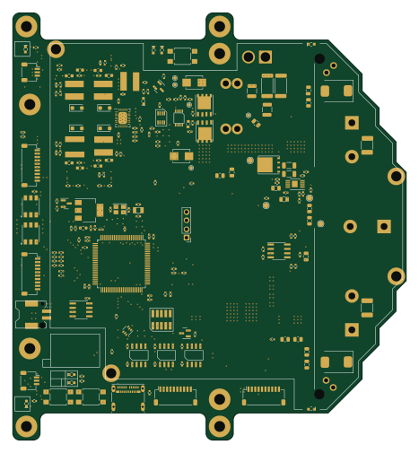
STM32Kicker
116 × 126 mm253 parts6LMIT6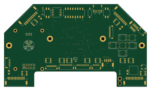 STM32
STM32Control
148 × 86 mm232 parts6LMIT6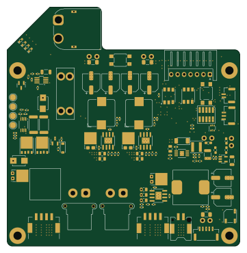 STM32
STM32Power Board
90 × 92.5 mm192 parts6LMIT6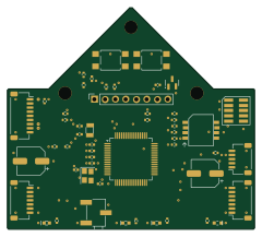 STM32
STM32Optical flow
60 × 53.7 mm49 parts4LMIT6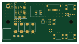 STM32
STM32Radio
65 × 34.8 mm32 parts4LMIT6 STM32
STM32Encoderboard
64 × 10 mm8 parts2LMIT6 STM32
STM32Adapter
41 × 22.5 mm7 parts2LMIT6
Breakbeam (Emitter)
22 × 52 mm7 parts2LMIT6
Breakbeam (Receiver)
22 × 52 mm4 parts2LMIT6
Similar boards

Stack chan
stack-chan
50 × 50 mm33 parts2LApache-2.01.7k
Cube batteryboard
willem-pennings
95 × 95 mm4 parts2LGPL-3.01.1k
Mesabob
rene-dev
87.5 × 50 mm44 parts2LGPL-3.0979
Bob
100 × 100 mm140 parts2LGPL-3.0979
Triple adapter
57 × 75 mm26 parts2LGPL-3.0979
Trollerv2
100 × 75 mm33 parts4LGPL-3.0979