
BatteryBoost

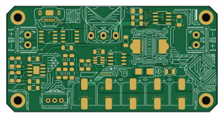
About the BatteryBoost PCB
BatteryBoost is an open source PCB design by stasiselectronics, published on GitHub under the CERN-OHL-S-2.0 license. It is a 2-layer board measuring 80 × 40 mm, with 40 components from 31 distinct parts.
Other key parts include the SP34063AEN, TP4056 and AP9101CK6. By type, the board carries 14 resistors, 9 capacitors, 4 diodes, 3 ICs, 3 transistors and 3 connectors.
It belongs with the power & battery designs in this gallery.
From the project
Open Source Hardware project for a battery powered DC voltage boost converter. Battery charge and protection integrated with an inexpensive Switch Mode Power Supply to convert 3.7 V to anywhere between 5 V and 24 V DC.
This respository contains the source files for a boost circuit designed to boost the voltage from a lithium battery to anywhere between 5 and 24 Volts.
The module includes a battery management system to help make recharging as easy as plugging in the microUSB cable.
This board has been designed in KiCAD, the wonderful open-source Electronics CAD software!
I have written an article on Hackster to explain some of the lessons learned while working on this design.
Main components on the BatteryBoost
BatteryBoost bill of materials (BOM)
40 components, 31 distinct parts.
| Qty | Part | Footprint | Refs |
|---|---|---|---|
| 1 | SP34063AEN | SOIC-8_3.9x4.9mm_P1.27mm | U1 |
| 1 | TP4056 | SOIC-8-1EP_3.9x4.9mm_P1.27mm_EP2.29x3mm | U2 |
| 1 | AP9101CK6 | SOT-23-6_Handsoldering | U3 |
| 1 | -40V 7.5A 2.5V @ 250uA 40mΩ @ 6A | SOP-8_3.9x4.9mm_P1.27mm | Q1 |
| 1 | -40V 7.5A 40mΩ @ 6A | SOP-8_3.9x4.9mm_P1.27mm | Q2 |
| 1 | 20V 7.5A 24mΩ @ 2.5Vgs | SOIC-8_3.9x4.9mm_P1.27mm | Q4 |
| 1 | USB_B_Micro | U-F-M5DD-Y-L | J5 |
| 1 | Battery | WJ124-3.81-2P | J6 |
| 1 | Output | WJ124-3.81-2P | J7 |
| 1 | Variable Resistors 500kΩ ±10% | Potentiometer_3296W-1-504 | RV1 |
| 1 | SW_SPDT | Switch_SS-12D06L5 | SW1 |
| 2 | Blue LED | D_1206_3216Metric_Pad1.42x1.75mm_HandSolder | D1, D4 |
| 1 | 40V 3A 500mV@3A | D_SMB | D2 |
| 1 | Red LED | D_1206_3216Metric_Pad1.42x1.75mm_HandSolder | D3 |
| 1 | 150uH ±20% 2.15A 280mΩ | Inductor_SLH_12x12x8_HandSolder | L1 |
| 1 | 1uH ±20% 3.29A 59mΩ | L_2.5x2.0_Hand_Solder | L2 |
| 4 | 100uF ±20% 50V | CP_Elec_8x10.5 | C1, C4, C6, C7 |
| 2 | 10uF ±10% 25V X5R | C_1206_3216Metric_Pad1.33x1.80mm_HandSolder | C2, C5 |
| 1 | 1.5nF ±10% 50V X7R 1206 | C_1206_3216Metric_Pad1.33x1.80mm_HandSolder | C3 |
| 1 | 100uF ±20% 50V (x3) | CP_Elec_8x10.5 | C8 |
Show 11 more
| Qty | Part | Footprint | Refs |
|---|---|---|---|
| 1 | 100nF ±10% 50V X7R | C_1206_3216Metric_Pad1.33x1.80mm_HandSolder | C9 |
| 1 | 0.3R | R_1206_3216Metric_Pad1.30x1.75mm_HandSolder | R1 |
| 1 | 180R | R_1206_3216Metric_Pad1.30x1.75mm_HandSolder | R2 |
| 1 | 499k 0.25W 1% | R_1206_3216Metric_Pad1.30x1.75mm_HandSolder | R3 |
| 1 | 16k | R_1206_3216Metric_Pad1.30x1.75mm_HandSolder | R4 |
| 4 | 10k | R_1206_3216Metric_Pad1.30x1.75mm_HandSolder | R5, R8, R10, R12 |
| 1 | 9.1k 1% 0.25W | R_1206_3216Metric_Pad1.30x1.75mm_HandSolder | R6 |
| 1 | 0R | R_1206_3216Metric_Pad1.30x1.75mm_HandSolder | R7 |
| 1 | 47.5kΩ ±1% 0.25W | R_1206_3216Metric_Pad1.30x1.75mm_HandSolder | R9 |
| 2 | 1.2kΩ ±1% 0.25W | R_1206_3216Metric_Pad1.30x1.75mm_HandSolder | R11, R16 |
| 1 | 330R ±1% 0.25W | R_1206_3216Metric_Pad1.30x1.75mm_HandSolder | R15 |
BatteryBoost design files
The KiCad project lives in the stasiselectronics/BatteryBoost repository on GitHub; these links point at the commit this page was built from.
- LayoutBatteryBoost.kicad_pcb
BatteryBoost: common questions
How big is the BatteryBoost PCB?
The BatteryBoost measures 80 × 40 mm, has 2 copper layers and is 1.6 mm thick.
How many components are on the BatteryBoost?
40 components, from 31 distinct parts. The full bill of materials is listed on this page.
Where can I download the BatteryBoost design files?
From the stasiselectronics/BatteryBoost repository on GitHub, which has the KiCad layout; the links under Design files point to each one.
Can I use the BatteryBoost design in my own project?
Yes, under the terms of its CERN-OHL-S-2.0 license, which stasiselectronics chose for the repository.
Similar boards

Stack chan
stack-chan
50 × 50 mm33 parts2LApache-2.01.7k
Display Carrier
AxxAxx
35.6 × 58.2 mm5 parts2LGPL-3.01.7k
ControllerCurrentShuntAddOn
stuartpittaway
26 × 16.9 mm9 parts2LCC-BY-NC-4.01.1k
Module 16S PassiveBalanceAddOn
61 × 74 mm86 parts2LCC-BY-NC-4.01.1k
TemperaturePCB PANEL
116 × 75.5 mm178 parts2LCC-BY-NC-4.01.1k
ProgrammingAdapter
10.5 × 83 mm3 parts2LCC-BY-NC-4.01.1k