
Inverter card 2

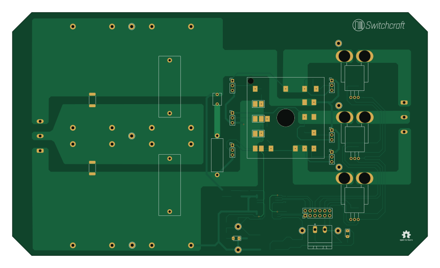
About the Inverter card 2 PCB
Inverter card 2 is an open source PCB design by switchcraft, published on GitHub. It is a 4-layer board measuring 215 × 126 mm, with 69 components from 33 distinct parts.
Other key parts include the ACS758xCB-PFF, ISE0505A-H and ACPL-C87B. By type, the board carries 21 capacitors, 18 resistors, 10 connectors, 10 test points, 6 ICs and 2 diodes.
It belongs with the sensors designs in this gallery.
From the project
KiCad Project files, schematic files, layout files and netlists
Inverter circuit board for Semikron IGBT/SiC module.
Features connections to gatedrivers and motor output. Voltage and temperature measurement through isolation amplifiers. Three phase output current measurement through hall-effect sensors.
This card is designed to sit on top of the DC-link capacitors. The board is designed for a no-load DC-link voltage of 565V.
Main components on the Inverter card 2
Inverter card 2 bill of materials (BOM)
69 components, 33 distinct parts.
| Qty | Part | Footprint | Refs |
|---|---|---|---|
| 3 | ACS758xCB-PFF | ACS758LCB-050B-PFF-T | U11, U12, U13 |
| 1 | ISE0505A-H | SMDIP-8_W7.62mm | U30 |
| 2 | ACPL-C87B | SSO-8_6.8x5.9mm_P1.27mm_Clearance8mm | U40, U50 |
| 1 | CONN_02X06 | PinHeader_2x06_P2.54mm_Vertical | J11 |
| 2 | CONN_01X03 | PhoenixContact_GMSTBA_2,5_3-G-7,62_1x03_P7.62mm_Horizontal | P0, P7 |
| 6 | CONN_01X03 | PinHeader_1x03_P2.54mm_Vertical | P1, P2, P3, P4, P5, P6 |
| 1 | CONN_01X02 | PhoenixContact_MSTBA_2,5_2-G-5,08_1x02_P5.08mm_Horizontal | P20 |
| 1 | 10uF | CP_Elec_6.3x7.7 | CP21 |
| 1 | SKiiP_13ACM12V18 | SKiiP_13ACM12V18 | T1 |
| 3 | TEST | TestPoint_Loop_D2.60mm_Drill1.6mm_Beaded | TP7, TP8, TP9 |
| 1 | DC_MID | TestPoint_Loop_D2.60mm_Drill1.6mm_Beaded | TP10 |
| 1 | DC+ | TestPoint_Loop_D2.60mm_Drill1.6mm_Beaded | TP11 |
| 1 | DC- | TestPoint_Loop_D2.60mm_Drill1.6mm_Beaded | TP12 |
| 1 | VCC | TestPoint_Loop_D2.60mm_Drill1.6mm_Beaded | TP21 |
| 1 | GND | TestPoint_Loop_D2.60mm_Drill1.6mm_Beaded | TP22 |
| 1 | VCC_ISO | TestPoint_Loop_D2.60mm_Drill1.6mm_Beaded | TP31 |
| 1 | GND_ISO | TestPoint_Loop_D2.60mm_Drill1.6mm_Beaded | TP32 |
| 2 | GREEN | LED_1206_3216Metric_Pad1.42x1.75mm_HandSolder | D21, D31 |
| 4 | 50uF | Panasonic_EZPE80506MTA | C1, C2, C3, C4 |
| 2 | 5uF | C_Rect_L31.5mm_W11.0mm_P27.50mm_MKS4 | C5, C6 |
Show 13 more
| Qty | Part | Footprint | Refs |
|---|---|---|---|
| 1 | 22pF | C_Disc_D6.0mm_W4.4mm_P5.00mm | C7 |
| 8 | 100nF | C_1206_3216Metric_Pad1.42x1.75mm_HandSolder | C11, C12, C13, C14, C15, C16, C43, C53 |
| 1 | 10nF | C_1206_3216Metric_Pad1.42x1.75mm_HandSolder | C22 |
| 1 | 10uF | C_1210_3225Metric_Pad1.42x2.65mm_HandSolder | C31 |
| 2 | 100pF | C_1210_3225Metric_Pad1.42x2.65mm_HandSolder | C41, C51 |
| 2 | 100nF | C_1210_3225Metric_Pad1.42x2.65mm_HandSolder | C42, C52 |
| 7 | 100k | R_1206_3216Metric_Pad1.42x1.75mm_HandSolder | R1, R2, R3, R4, R5, R6, R41 |
| 1 | 5 | R_Axial_DIN0617_L17.0mm_D6.0mm_P20.32mm_Horizontal | R7 |
| 2 | 200k | R_2512_6332Metric_Pad1.52x3.35mm_HandSolder | R8, R9 |
| 3 | 250 | R_1206_3216Metric_Pad1.42x1.75mm_HandSolder | R11, R12, R13 |
| 2 | 1250 | R_1206_3216Metric_Pad1.42x1.75mm_HandSolder | R21, R31 |
| 2 | 2.7M | R_1210_3225Metric_Pad1.42x2.65mm_HandSolder | R51, R52 |
| 1 | 20k | R_1206_3216Metric_Pad1.42x1.75mm_HandSolder | R53 |
Inverter card 2 design files
The KiCad project lives in the switchcraft/kicad-projects repository on GitHub; these links point at the commit this page was built from.
Inverter card 2: common questions
How big is the Inverter card 2 PCB?
The Inverter card 2 measures 215 × 126 mm, has 4 copper layers and is 1.6 mm thick.
How many components are on the Inverter card 2?
69 components, from 33 distinct parts. The full bill of materials is listed on this page.
Where can I download the Inverter card 2 design files?
From the switchcraft/kicad-projects repository on GitHub, which has the KiCad layout; the links under Design files point to each one.
Can I use the Inverter card 2 design in my own project?
The repository has no license, so all rights stay with switchcraft. Use it as a reference, and ask the author before reusing the design.
More boards in kicad-projects
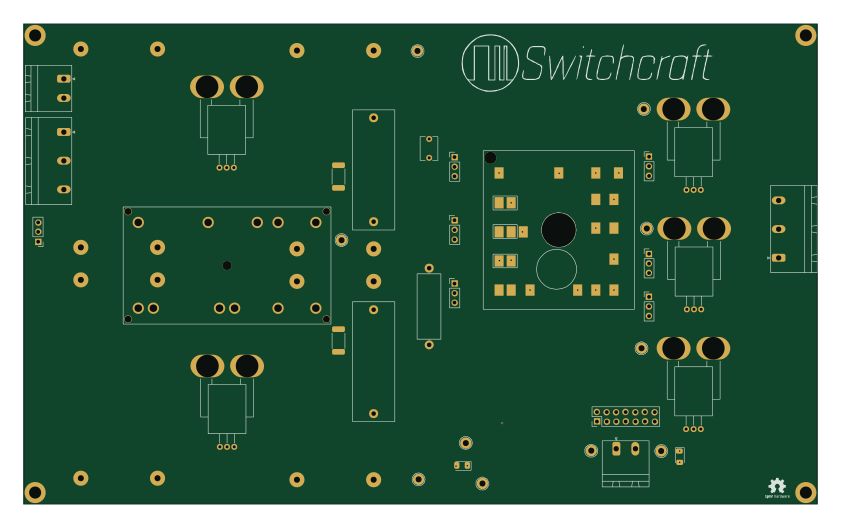
FrontEnd Inverter
210 × 127 mm80 parts4LNo license6
Production1
156 × 80 mm60 parts2LNo license6
Pre charge controller
126 × 52.2 mm56 parts2LNo license6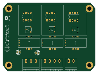
Current Sensing Card
95 × 70 mm40 parts2LNo license6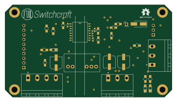
Gate driver
90 × 50 mm33 parts2LNo license6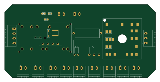
Main Power Electronics Connection Card (M.P.E.C.C)
154.8 × 75.2 mm25 parts2LNo license6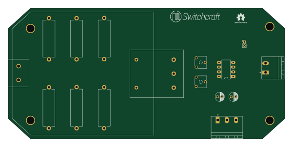
Voltage Sensor Card
150 × 71 mm23 parts2LNo license6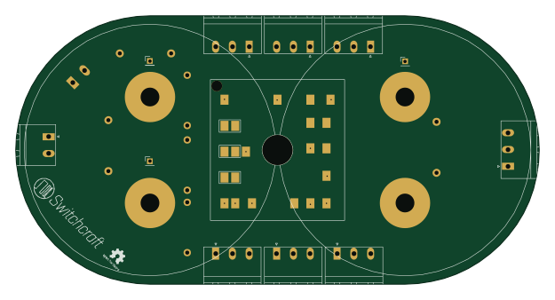
Inverter card
156 × 80 mm21 parts2LNo license6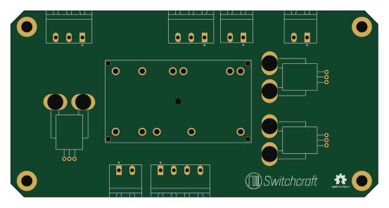
Diode Front-End Connector Card
138 × 70 mm19 parts2LNo license6
Similar boards

Sensor smd
scottbez1
40 × 20 mm5 parts2LApache-2.04.2k
Sensors
StuckAtPrototype
15.2 × 9 mm14 parts4LApache-2.03.8k
Microphone
Mentra-Community
5.5 × 6.1 mm6 parts2LMIT1.2k
TemperaturePCB PANEL
stuartpittaway
116 × 75.5 mm178 parts2LCC-BY-NC-4.01.1k
Pots
shanteacontrols
390 × 93 mm75 parts2LApache-2.0956
ButtonsLEDs
390 × 37 mm82 parts2LApache-2.0956