
Soldered-MQ-breakouts easyC-hardware design

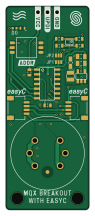
About the Soldered-MQ-breakouts easyC-hardware design PCB
Soldered-MQ-breakouts easyC-hardware design is an open source AVR/Arduino PCB design by test-gh-syncer2, published on GitHub under the TAPR-OHL-1.0 license. It is a 2-layer board measuring 22 × 54 mm, with 24 components from 16 distinct parts.
Its main chip is the ATTINY404-SSNR, from the AVR/Arduino family. Other key parts include the MQ-X, NMOS-DUAL and TPS613222A. By type, the board carries 6 resistors, 4 ICs, 4 relays, 4 capacitors, 2 jumpers and 1 diode.
It belongs with the dev boards & breakouts designs in this gallery.
From the project
Hardware design, BOM, gerbers, 3D files and pinout for MQ_breakouts_easyC designed by Soldered.
Find XXXXXXXX on our [web store](https://solde.red/ .
All Soldered hardware is designed in KiCAD, and repositories are organised in the following way:
- CAD folder - contains KiCAD files (Schematics, Board, Panel Board), organised by version. Change log lists all changes between different versions. - OUTPUTS - contains useful files, such as Bill of Materials (BOM), PDF of schematics, 3D .step file of the board and gerber files, organised by version.
Main components on the Soldered-MQ-breakouts easyC-hardware design
Soldered-MQ-breakouts easyC-hardware design bill of materials (BOM)
24 components, 16 distinct parts — part numbers from the project's BOM.
| Qty | Part | Footprint | Refs |
|---|---|---|---|
| 1 | MQ-X | MQ | U1 |
| 1 | NMOS-DUAL | SOT-363 | U2 |
| 1 | TPS613222A | tps613222a | U3 |
| 1 | ATTINY404-SSNR | SOIC-14 | U4 |
| 2 | HOLE_3.2MM HOLE_3.2mm | HOLE_3.2mm | H1, H2 |
| 2 | SMD_JUMPER_3_PAD_TRACE | SMD_JUMPER_3_PAD_TRACE | JP1, JP2 |
| 2 | easyC-SMD | easyC-connector | K1, K3 |
| 1 | HEADER-UPDI | HEADER-UPDI | K2 |
| 1 | DSHP03TS-S | DSHP03TS-S | K4 |
| 1 | purple | 0402LED | D1 |
| 1 | DFE201612E-2R2M=P2 | 0806L | L1 |
| 2 | CL10A226MPCNUBE | 0805C | C1, C2 |
| 1 | C1608X7S1A475K080AC | 0805C | C3 |
| 1 | 0.1UF 0.1uF | 0603C | C4 |
| 5 | 10K 10k | 0603R | R1, R2, R3, R4, R5 |
| 1 | 2K2 2k2 | 0402R | R6 |
Soldered-MQ-breakouts easyC-hardware design design files
The KiCad project lives in the test-gh-syncer2/Soldered-MQ-breakouts-easyC-hardware-design repository on GitHub; these links point at the commit this page was built from.
Soldered-MQ-breakouts easyC-hardware design: common questions
What microcontroller does the Soldered-MQ-breakouts easyC-hardware design use?
The Soldered-MQ-breakouts easyC-hardware design is built around the ATTINY404-SSNR, from the AVR/Arduino family.
How big is the Soldered-MQ-breakouts easyC-hardware design PCB?
The Soldered-MQ-breakouts easyC-hardware design measures 22 × 54 mm, has 2 copper layers and is 1.6 mm thick.
How many components are on the Soldered-MQ-breakouts easyC-hardware design?
24 components, from 16 distinct parts, with part numbers taken from the project's own BOM. The full bill of materials is listed on this page.
Where can I download the Soldered-MQ-breakouts easyC-hardware design design files?
From the test-gh-syncer2/Soldered-MQ-breakouts-easyC-hardware-design repository on GitHub, which has the KiCad layout, the schematic and the BOM; the links under Design files point to each one.
Can I use the Soldered-MQ-breakouts easyC-hardware design design in my own project?
Yes, under the terms of its TAPR-OHL-1.0 license, which test-gh-syncer2 chose for the repository.
Can I test firmware for the Soldered-MQ-breakouts easyC-hardware design without the hardware?
Yes. HardLabs builds a simulation of the board from its netlist and BOM, so you can run and debug AVR/Arduino firmware against it before you order a PCB.
Similar boards
 AVR/Arduino
Magspoof
samyk
35 × 29 mm11 parts2LNo license4.2k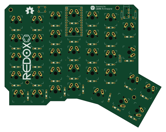 AVR/Arduino
Redox keyboard
mattdibi
162.2 × 126.5 mm77 parts2LMIT2.0k AVR/Arduino
Labrador
espotek-org
36.8 × 34.7 mm75 parts2LNo license1.2k AVR/Arduino
ModuleV450
stuartpittaway
30 × 61.4 mm39 parts2LCC-BY-NC-4.01.1k AVR/Arduino
V4
30 × 50 mm38 parts2LCC-BY-NC-4.01.1k AVR/Arduino
Discipline
coseyfannitutti
304.9 × 122.8 mm170 parts2LCC-BY-NC-4.01.0k