
USB--Bridge-Module

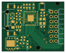
About the USB--Bridge-Module
USB--Bridge-Module is an open source RP2040/RP2350 PCB design by TheLordOmega, published on GitHub under the MIT license. It is a 2-layer board measuring 32 × 25.5 mm, with 35 components from 18 distinct parts.
Its main chip is the RP2040, from the RP2040/RP2350 family. Other key parts include the AP2112K-3.3, USBLC6-2P6 and W25Q64JVZPIQ. By type, the board carries 15 capacitors, 7 resistors, 4 ICs, 4 switches, 2 connectors and 1 crystal.
From the project
a module to use the console as an input
A module that forwards controller input received over the console's J1 bus out to a phone, laptop, or SBC as a standard USB HID gamepad.
Key features: Receives button/stick state from the console over UART (J1) Presents as a real USB HID gamepad to whatever it's plugged into * Built on an unmodified, pre-routed RP2040 gamepad PCB design (not a from-scratch board).
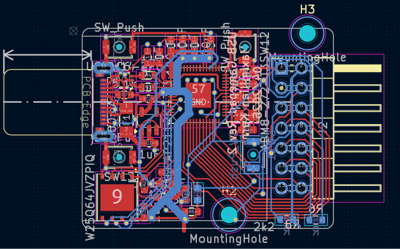
Main components on the USB--Bridge-Module
USB--Bridge-Module bill of materials (BOM)
35 components, 18 distinct parts — part numbers from the project's BOM.
| Qty | Part | Footprint | Refs |
|---|---|---|---|
| 1 | AP2112K-3.3 | SOT-23-5 | U1 |
| 1 | USBLC6-2P6 | SOT-666 | U2 |
| 1 | W25Q64JVZPIQ | WSON-8-1EP_6x5mm_P1.27mm_EP3.4x4.3mm | U3 |
| 1 | RP2040 | QFN-56-1EP_7x7mm_P0.4mm_EP3.2x3.2mm | U4 |
| 1 | ABM8-272-T3 | Crystal_SMD_Abracon_ABM8G-4Pin_3.2x2.5mm | Y1 |
| 1 | USB_C_RECEPTACLE_USB2.0 USB_C_Receptacle_USB2.0 | USB_TYPEC_PLUG_12P | J1 |
| 1 | ~ | Male_Module | J2 |
| 1 | 500MA 500mA | Fuse_1206_3216Metric_Pad1.42x1.75mm_HandSolder | F1 |
| 4 | SW_Push | SW_SPST_B3U-1000P-B | SW11, SW12, SW13, SW14 |
| 1 | LED | LED_0603_1608Metric | D1 |
| 5 | 1UF 1uF | C_0603_1608Metric | C1, C2, C3, C11, C13 |
| 8 | 100NF 100nF | C_0603_1608Metric | C4, C7, C8, C9, C10, C12, C14, C15 |
| 2 | 15PF 15pF | C_0603_1608Metric | C5, C6 |
| 1 | 1k | R_0603_1608Metric | R2 |
| 2 | 27 | R_0603_1608Metric | R3, R4 |
| 1 | 2K2 2k2 | R_0603_1608Metric | R5 |
| 2 | R | R_0603_1608Metric | R6, R8 |
| 1 | 5.1K 5.1k | R_0603_1608Metric | R7 |
USB--Bridge-Module design files
The KiCad project lives in the TheLordOmega/USB--Bridge-Module repository on GitHub; these links point at the commit this page was built from.
USB--Bridge-Module: common questions
What microcontroller does the USB--Bridge-Module use?
The USB--Bridge-Module is built around the RP2040, from the RP2040/RP2350 family.
How big is the USB--Bridge-Module?
The USB--Bridge-Module measures 32 × 25.5 mm, has 2 copper layers and is 1.6 mm thick.
How many components are on the USB--Bridge-Module?
35 components, from 18 distinct parts, with part numbers taken from the project's own BOM. The full bill of materials is listed on this page.
Where can I download the USB--Bridge-Module design files?
From the TheLordOmega/USB--Bridge-Module repository on GitHub, which has the KiCad layout, the schematic and the BOM; the links under Design files point to each one.
Can I use the USB--Bridge-Module design in my own project?
Yes, under the terms of its MIT license, which TheLordOmega chose for the repository.
Can I test firmware for the USB--Bridge-Module without the hardware?
Yes. HardLabs builds a simulation of the board from its netlist and BOM, so you can run and debug RP2040/RP2350 firmware against it before you order a PCB.
Similar boards
 RP2040/RP2350
OSO-BOOK-C1
joeycastillo
85 × 115 mm29 parts2LCC-BY-SA-4.08.1k RP2040/RP2350
Corne cherry
foostan
277.2 × 107.5 mm164 parts2LCC-BY-4.07.7k RP2040/RP2350
Corne chocolate
277.2 × 107.5 mm164 parts2LCC-BY-4.07.7k RP2040/RP2350
Jitx design
gusmanb
55.5 × 65 mm26 parts4LGPL-3.05.0k RP2040/RP2350
LogicAnalyzer
57 × 55.2 mm6 parts2LGPL-3.05.0k RP2040/RP2350
Main
google
98 × 71 mm102 parts2LApache-2.02.9k