
TFASPDIMU02

About the TFASPDIMU02 PCB
TFASPDIMU02 is an open source PCB design by ThunderFly-aerospace, published on GitHub under the GPL-3.0 license. It is a 2-layer board measuring 30 × 15 mm, with 40 components from 17 distinct parts.
Other key parts include the SDP3X, ICM-20948, PCA9617A, MIC5504-3.3YM5 and MIC5504-1.8YM5. By type, the board carries 13 capacitors, 12 resistors, 6 ICs, 4 modules, 2 jumpers and 2 diodes.
It belongs with the sensors designs in this gallery.
From the project
I²C bus differential pressure sensor with IMU and Magnetometer.
ThunderFly TFASPDIMU02 is I2C bus sensor board equipped with a differential pressure sensor (Sensirion SDP3x) and 9-axis motion tracking sensor (ICM-20948). The board is equipped with a 4-pin JST-GH connector. The sensor board is designed for multiple uses. It can be used as a self-adjusting anemometer WINDGAUGE03 or as an airspeed sensor for UAVs with optional function as the external magnetometer. The featured use (after firmware improvement) could be an angle of attract sensor, stall detector, or vibration (Flutter) detector.
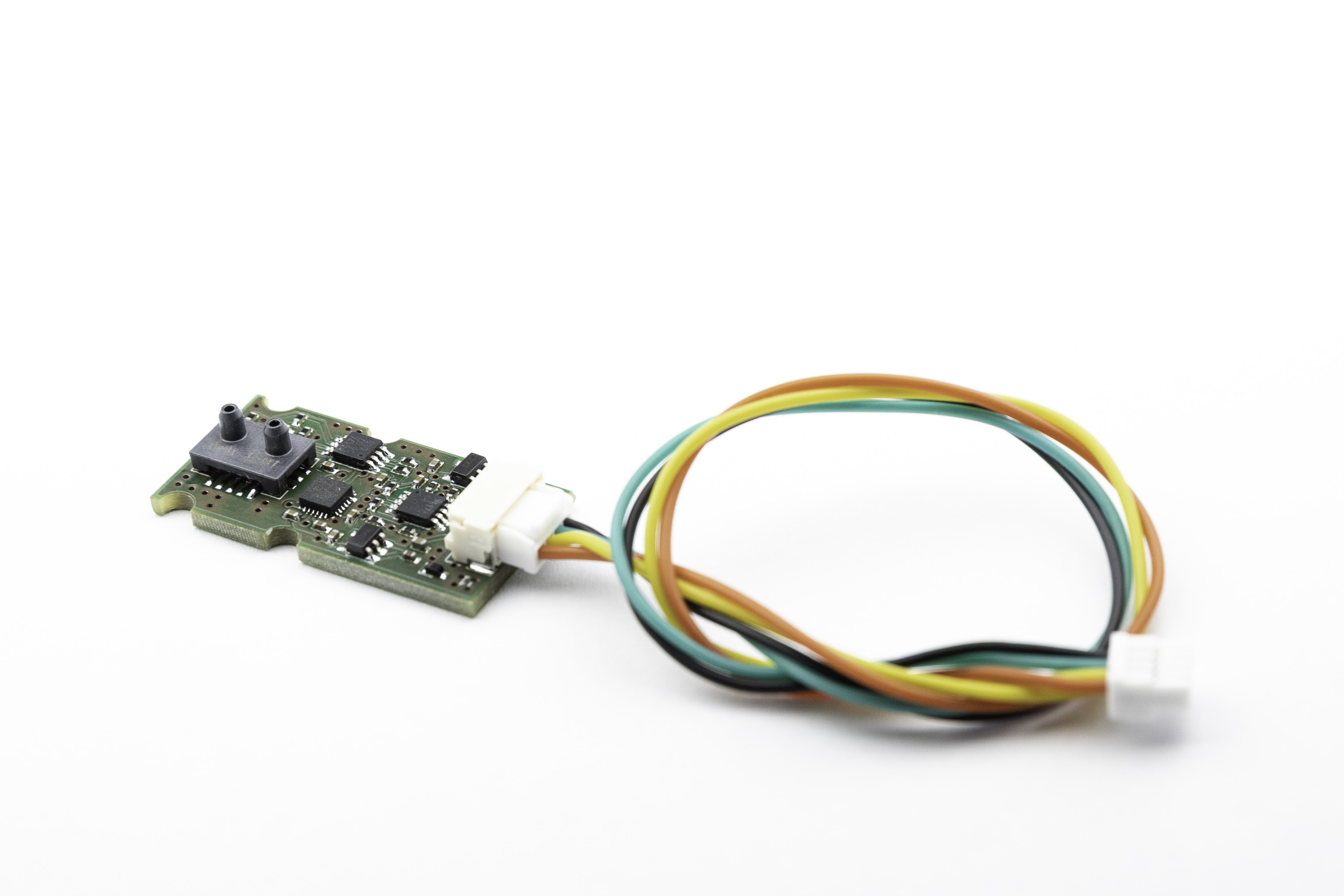
Main components on the TFASPDIMU02
TFASPDIMU02 bill of materials (BOM)
40 components, 17 distinct parts — part numbers from the project's BOM.
| Qty | Part | Footprint | Refs |
|---|---|---|---|
| 1 | SDP3X SDP3x | SDP3x | U1 |
| 1 | ICM-20948 | InvenSense_QFN-24_3x3mm_P0.4mm | U2 |
| 2 | PCA9617A | TSSOP-8_3x3mm_P0.65mm | U3, U6 |
| 1 | MIC5504-3.3YM5 MIC5504-3.3YM5-TR | SOT-23-5 | U4 |
| 1 | MIC5504-1.8YM5 MIC5504-1.8YM5-TR | SOT-23-5 | U5 |
| 4 | HOLE_TF | dira_3mm | M1, M2, M3, M7 |
| 1 | SM04B-GHS-TB | JST_GH_SM04B-GHS-TB_1x04-1MP_P1.25mm_Horizontal | J1 |
| 2 | SolderJumper_3_Bridged12 | SolderJumper-3_P1.3mm_Bridged12_RoundedPad1.0x1.5mm | JP1, JP2 |
| 1 | GREEN | LED_0603_1608Metric_Pad1.05x0.95mm_HandSolder | D1 |
| 1 | BZX585-B5V6.115 | D_SOD-523 | D2 |
| 8 | 100nF | C_0402_1005Metric | C1, C2, C3, C4, C9, C10, C12, C13 |
| 4 | 1uF | C_0402_1005Metric | C5, C6, C7, C8 |
| 1 | 10UF 10uF | C_0402_1005Metric | C11 |
| 2 | 75R | R_0402_1005Metric | R1, R11 |
| 3 | 2k7 | R_0402_1005Metric | R2, R3, R10 |
| 6 | 10k | R_0402_1005Metric | R4, R5, R6, R7, R8, R9 |
| 1 | 180R | R_0402_1005Metric | R12 |
TFASPDIMU02 design files
The KiCad project lives in the ThunderFly-aerospace/TFASPDIMU02 repository on GitHub; these links point at the commit this page was built from.
TFASPDIMU02: common questions
How big is the TFASPDIMU02 PCB?
The TFASPDIMU02 measures 30 × 15 mm, has 2 copper layers and is 1.6 mm thick.
How many components are on the TFASPDIMU02?
40 components, from 17 distinct parts, with part numbers taken from the project's own BOM. The full bill of materials is listed on this page.
Where can I download the TFASPDIMU02 design files?
From the ThunderFly-aerospace/TFASPDIMU02 repository on GitHub, which has the KiCad layout, the schematic and the BOM; the links under Design files point to each one.
Can I use the TFASPDIMU02 design in my own project?
Yes, under the terms of its GPL-3.0 license, which ThunderFly-aerospace chose for the repository.
Similar boards

Sensor smd
scottbez1
40 × 20 mm5 parts2LApache-2.04.2k
Sensors
StuckAtPrototype
15.2 × 9 mm14 parts4LApache-2.03.8k
Microphone
Mentra-Community
5.5 × 6.1 mm6 parts2LMIT1.2k
TemperaturePCB PANEL
stuartpittaway
116 × 75.5 mm178 parts2LCC-BY-NC-4.01.1k
Pots
shanteacontrols
390 × 93 mm75 parts2LApache-2.0956
USB
52 × 12.6 mm6 parts2LApache-2.0956