
Embedded frosty monitor

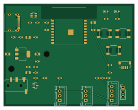
About the Embedded frosty monitor PCB
Embedded frosty monitor is an open source ESP32 PCB design by tomislacker, published on GitHub under the Apache-2.0 license. It is a 2-layer board measuring 70 × 55 mm, with 43 components from 26 distinct parts.
Its main chip is the ESP32-C3-MINI-1, from the ESP32 family. Other key parts include the USBLC6-2SC6 and AMS1117-3.3. By type, the board carries 15 resistors, 12 capacitors, 7 connectors, 3 ICs, 3 switches and 3 diodes.
It belongs with the iot & wireless and sensors designs in this gallery.
From the project
Portable diagnostic logger for frozen-drink machines: ESP32 firmware, current/vibration/temperature sensing, SD-card record set, Python analysis, AWS IoT via Terraform
This is the first custom PCB for the Guard tier described in docs/product-line.md (Tier 1): a permanent, every-machine monitor board built around a pre-certified ESP32-C3-MINI-1 module. SELV only -- nothing above 5V ever touches this board.
- A complete SKiDL schematic (schematic.py) covering every circuit block in the spec: MCU, USB-C power+data with ESD protection, 3.3V regulation, CT current-sense front end, 2x DS18B20 headers, drip-counter header, status/alert LEDs, ack/BOOT/RESET buttons, I2C (Qwiic) and UART expansion headers, 2x M3 mounting holes. - SKiDL ERC passes clean: 0 errors, 0…
Main components on the Embedded frosty monitor
Embedded frosty monitor bill of materials (BOM)
43 components, 26 distinct parts — part numbers from the project's BOM.
| Qty | Part | Footprint | Refs |
|---|---|---|---|
| 1 | ESP32-C3-MINI-1 ESP32-C3-MINI-1 (schematic symbol: ESP32-C3-WROOM-02, same SoC/pinout) | ESP32-C3-WROOM-02 | U1 |
| 1 | USBLC6-2SC6 | SOT-23-6 | U2 |
| 1 | AMS1117-3.3 | SOT-223 | U3 |
| 1 | USB-C receptacle (5V power + USB2.0 data, no PD) | USB_C_Receptacle_HRO_TYPE-C-31-M-12 | J1 |
| 1 | 3.5mm TRS (SCT-013-020 burden output, 1V RMS @ rated current) | Jack_3.5mm_PJ320D_Horizontal | J2 |
| 1 | DS18B20 chain 1 (pin1 GND / pin2 DQ / pin3 3V3) | JST_XH_B3B-XH-A_1x03_P2.50mm_Vertical | J3 |
| 1 | DS18B20 chain 2 (pin1 GND / pin2 DQ / pin3 3V3) | JST_XH_B3B-XH-A_1x03_P2.50mm_Vertical | J4 |
| 1 | Drip counter (pin1 3V3 / pin2 GND / pin3 SIG / pin4 spare) | JST_XH_B4B-XH-A_1x04_P2.50mm_Vertical | J5 |
| 1 | I2C expansion, Qwiic pinout (pin1 GND / pin2 3V3 / pin3 SDA / pin4 SCL) | JST_SH_BM04B-SRSS-TB_1x04-1MP_P1.00mm_Vertical | J6 |
| 1 | UART debug (pin1 TX / pin2 RX / pin3 GND) | PinHeader_1x03_P2.54mm_Vertical | J7 |
| 1 | Ack button (user) | SW_SPST_SKQG_WithoutStem | SW1 |
| 1 | BOOT button (GPIO9, conventional strap-to-GND) | SW_SPST_SKQG_WithoutStem | SW2 |
| 1 | RESET button (EN-to-GND) | SW_SPST_SKQG_WithoutStem | SW3 |
| 1 | BAT54S | SOT-23 | D1 |
| 1 | Status LED (green) | LED_0603_1608Metric | D2 |
| 1 | Alert LED (red) | LED_0603_1608Metric | D3 |
| 6 | 100nF | C_0603_1608Metric | C1, C3, C5, C8, C11, C12 |
| 4 | 10uF | C_0805_2012Metric | C2, C4, C6, C10 |
| 1 | 22uF | C_0805_2012Metric | C7 |
| 1 | 1uF | C_0603_1608Metric | C9 |
Show 6 more
| Qty | Part | Footprint | Refs |
|---|---|---|---|
| 4 | 10k | R_0603_1608Metric | R1, R6, R7, R10 |
| 2 | 5.1k | R_0603_1608Metric | R2, R3 |
| 2 | 22 | R_0603_1608Metric | R4, R5 |
| 2 | 1k | R_0603_1608Metric | R8, R11 |
| 3 | 4.7k | R_0603_1608Metric | R9, R14, R15 |
| 2 | 330 | R_0603_1608Metric | R12, R13 |
Embedded frosty monitor design files
The KiCad project lives in the tomislacker/embedded-frosty-monitor repository on GitHub; these links point at the commit this page was built from.
Embedded frosty monitor: common questions
What microcontroller does the Embedded frosty monitor use?
The Embedded frosty monitor is built around the ESP32-C3-MINI-1, from the ESP32 family.
How big is the Embedded frosty monitor PCB?
The Embedded frosty monitor measures 70 × 55 mm, has 2 copper layers and is 1.6 mm thick.
How many components are on the Embedded frosty monitor?
43 components, from 26 distinct parts, with part numbers taken from the project's own BOM. The full bill of materials is listed on this page.
Where can I download the Embedded frosty monitor design files?
From the tomislacker/embedded-frosty-monitor repository on GitHub, which has the KiCad layout and the BOM; the links under Design files point to each one.
Can I use the Embedded frosty monitor design in my own project?
Yes, under the terms of its Apache-2.0 license, which tomislacker chose for the repository.
Can I test firmware for the Embedded frosty monitor without the hardware?
Yes. HardLabs builds a simulation of the board from its netlist and BOM, so you can run and debug ESP32 firmware against it before you order a PCB.
Similar boards
 ESP32
OSO-BOOK-B1
joeycastillo
85 × 115 mm65 parts2LCC-BY-SA-4.08.1k ESP32
Powertrain
byrantech
64 × 45.4 mm171 parts4LMIT4.3k ESP32
Badge
atopile
56.3 × 39 mm239 parts4LMIT4.0k ESP32
Esp32 minimal
36.2 × 26.8 mm20 parts2LMIT4.0k ESP32
Controller
StuckAtPrototype
29 × 74 mm58 parts4LApache-2.03.8k ESP32
Racer
36 × 50.2 mm70 parts4LApache-2.03.8k