
Modulo-Lector

About the Modulo-Lector PCB
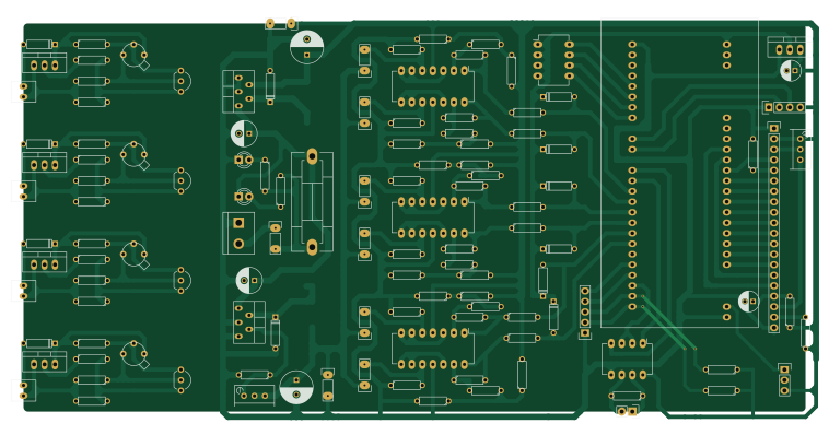
Modulo-Lector is an open source NXP PCB design by vecchiettidaniel, published on GitHub. It is a 2-layer board measuring 189.2 × 94 mm, with 99 components from 98 distinct parts.
Its main chip is the LPC1769-54Pines, from the NXP family. Other key parts include the MAX485, LM2575-ADJ, LM2575-5, RegLin-G-O-I and LM317T. By type, the board carries 49 resistors, 15 connectors, 11 diodes, 6 ICs, 6 capacitors and 2 switches.
Main components on the Modulo-Lector
Modulo-Lector bill of materials (BOM)
99 components, 98 distinct parts.
| Qty | Part | Footprint | Refs |
|---|---|---|---|
| 1 | MAX485 | DIP-8_W7.62mm_LongPads | U101 |
| 1 | LM2575-ADJ | TO-220-x5-(3_2) | U201 |
| 1 | LM2575-5 | TO-220-x5-(2_3) | U202 |
| 1 | RegLin-G-O-I | TO-220_Neutral123_Vertical | U203 |
| 1 | LM317T | TO-220_Neutral123_Vertical | U401 |
| 1 | LM35 | TO-92_Inline_Wide | U402 |
| 1 | 2N2907 | TBJ-To18 | Q401 |
| 1 | WG12864A-GLCD | Pin_Header_Straight_1x20 | P101 |
| 1 | RS485 | Pin_Header_Straight_1x02 | P102 |
| 1 | Teclado | Pin_Header_Straight_1x05 | P103 |
| 1 | CONN_01X03 | Pin_Header_Straight_1x03 | P104 |
| 1 | CONN_01X04 | Pin_Header_Straight_1x04 | P105 |
| 1 | POWER_IN_7-40[v] | bornier2 | P201 |
| 1 | POWER_Out-(+5V) | Pin_1x2_Paso | P202 |
| 1 | PWR_Out-Reg | Pin_1x2_Paso | P203 |
| 1 | L1-IN | Pin_1x2_Paso | P301 |
| 1 | L3-IN | Pin_1x2_Paso | P302 |
| 1 | L5-IN | Pin_1x2_Paso | P303 |
| 1 | L2-IN | Pin_1x2_Paso | P304 |
| 1 | L4-IN | Pin_1x2_Paso | P305 |
Show 78 more
| Qty | Part | Footprint | Refs |
|---|---|---|---|
| 1 | L6-IN | Pin_1x2_Paso | P306 |
| 1 | Loop_IN | Pin-1x2 | P401 |
| 1 | Fuse | Fuseholder5x20_horiz_SemiClosed_Casing10x25mm | F201 |
| 1 | LPC1769-54Pines | LPC1769_Stick-54-pins | LPC1769-N101 |
| 1 | LM324-A | DIP-14_W7.62mm_LongPads | OP301 |
| 1 | LM324-B | DIP-14_W7.62mm_LongPads | OP302 |
| 1 | LM324-C | DIP-14_W7.62mm_LongPads | OP303 |
| 1 | GLCD-15k | Potentiometer_Bourns_3296W_3-8Zoll_Inline_ScrewUp | RV101 |
| 1 | ADJ_POT | Potentiometer_Bourns_3296W_3-8Zoll_Inline_ScrewUp | RV201 |
| 1 | SW_DIP_x4 | DIP-8_W7.62mm_LongPads | S101 |
| 1 | Power ON/OFF | Pin_1x2_Paso | SW201 |
| 1 | Dp-1N5817-L1 | D3 | D101 |
| 1 | Dp-1N5817-L2 | D3 | D102 |
| 1 | Dp-1N5817-L3 | D3 | D103 |
| 1 | Dp-1N5817-L4 | D3 | D104 |
| 1 | Dp-1N5817-L5 | D3 | D105 |
| 1 | Dp-1N5817-L6 | D3 | D106 |
| 1 | LED_FUSE | LED-3MM | D201 |
| 1 | PWR_ON_LED | LED-3MM | D202 |
| 1 | ADJ_1N5819 | D3 | D203 |
| 1 | 5v_1N5819 | D3 | D204 |
| 1 | 1N4007 | D3 | D401 |
| 1 | 5v_330uH | Neosid_Inductor_SM-NE127 | L201 |
| 1 | ADJ_330uH | Neosid_Inductor_SM-NE127 | L202 |
| 1 | GLCD-100uF | C_Radial_D5_L11_P2 | C101 |
| 1 | ADJ_100uF(25v) | C_Radial_D6.3_L11.2_P2.5 | C201 |
| 1 | 5v_100uF(25v) | C_Radial_D6.3_L11.2_P2.5 | C202 |
| 1 | ADJ_330uF(25v) | C_Radial_D8_L11.5_P3.5 | C203 |
| 1 | 5v_330uF | C_Radial_D8_L13_P3.8 | C204 |
| 1 | 3v3_100uF | C_Radial_D5_L11_P2 | C205 |
| 1 | P0.27_Pull_Up | R3 | R1 |
| 1 | P0.28_Pull_Up | R3 | R2 |
| 2 | GLCD-10K | R3 | R101, R102 |
| 1 | GLCD-100 | R3 | R103 |
| 1 | Rp-1k-L1 | R3 | R104 |
| 1 | Rp-1k-L2 | R3 | R105 |
| 1 | Rp-1k-L3 | R3 | R106 |
| 1 | Rp-1k-L4 | R3 | R107 |
| 1 | Rp-1k-L5 | R3 | R108 |
| 1 | Rp-1k-L6 | R3 | R109 |
| 1 | RS485-120 | R3 | R110 |
| 1 | PWR_Fuse_R | R3 | R201 |
| 1 | PWR_ON_R | R3 | R202 |
| 1 | ADJ-R1(1k) | R3 | R203 |
| 1 | L1-RG1-2k2 | R3 | R301 |
| 1 | L3-RG1-2k2 | R3 | R302 |
| 1 | L5-RG1-2k2 | R3 | R303 |
| 1 | L1-RG2-1k2 | R3 | R304 |
| 1 | L1-Rin-120 | R3 | R305 |
| 1 | L3-RG2-1k2 | R3 | R306 |
| 1 | L3-Rin-120 | R3 | R307 |
| 1 | L5-RG2-1k2 | R3 | R308 |
| 1 | L5-Rin-120 | R3 | R309 |
| 1 | L2-RG2-1k2 | R3 | R310 |
| 1 | L2-Rin-120 | R3 | R311 |
| 1 | L4-RG2-1k2 | R3 | R312 |
| 1 | L4-Rin-120 | R3 | R313 |
| 1 | L6-RG2-1k2 | R3 | R314 |
| 1 | L6-Rin-120 | R3 | R315 |
| 1 | L2-RG1-2k2 | R3 | R316 |
| 1 | L4-RG1-2k2 | R3 | R317 |
| 1 | L6-RG1-2k2 | R3 | R318 |
| 1 | L2-Ra1-4k7 | R3 | R319 |
| 1 | L3-Ra1-4k7 | R3 | R320 |
| 1 | L2-Ra2-1k | R3 | R321 |
| 1 | L3-Ra2-1k | R3 | R322 |
| 1 | L1-Ra1-4k7 | R3 | R323 |
| 1 | L5-Ra1-4k7 | R3 | R324 |
| 1 | L1-Ra2-1k | R3 | R325 |
| 1 | L5-Ra2-1k | R3 | R326 |
| 1 | L6-Ra1-4k7 | R3 | R327 |
| 1 | L4-Ra1-4k7 | R3 | R328 |
| 1 | L6-Ra2-1k | R3 | R329 |
| 1 | L4-Ra2-1k | R3 | R330 |
| 1 | 330 | R3 | R401 |
| 1 | 120 | R3 | R402 |
| 1 | 4.7k | R3 | R403 |
| 1 | 36 | R3 | R404 |
Modulo-Lector design files
The KiCad project lives in the vecchiettidaniel/caja-negra repository on GitHub; these links point at the commit this page was built from.
Modulo-Lector: common questions
What microcontroller does the Modulo-Lector use?
The Modulo-Lector is built around the LPC1769-54Pines, from the NXP family.
How big is the Modulo-Lector PCB?
The Modulo-Lector measures 189.2 × 94 mm, has 2 copper layers and is 1.6 mm thick.
How many components are on the Modulo-Lector?
99 components, from 98 distinct parts. The full bill of materials is listed on this page.
Where can I download the Modulo-Lector design files?
From the vecchiettidaniel/caja-negra repository on GitHub, which has the KiCad layout; the links under Design files point to each one.
Can I use the Modulo-Lector design in my own project?
The repository has no license, so all rights stay with vecchiettidaniel. Use it as a reference, and ask the author before reusing the design.
Can I test firmware for the Modulo-Lector without the hardware?
Yes. HardLabs builds a simulation of the board from its netlist and BOM, so you can run and debug NXP firmware against it before you order a PCB.
More boards in caja-negra
Similar boards
 NXP
32Bit shift register
MaltWhiskey
100 × 54 mm56 parts4LNo license763 NXP
Mega-Cube-Board
200 × 54 mm100 parts4LNo license763 NXP
MCL6809
MicroCoreLabs
32.3 × 61 mm7 parts4LNo license532 NXP
MCL68
31.6 × 84.1 mm13 parts4LNo license532 NXP
MCL65+
72.6 × 64.1 mm6 parts2LNo license532 NXP
MCLZ8
37.1 × 61.5 mm6 parts4LNo license532