
ATMEGA8A-Tutorial-Board-I

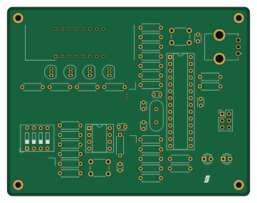
About the ATMEGA8A-Tutorial-Board-I
ATMEGA8A-Tutorial-Board-I is an open source AVR/Arduino PCB design by villseriol, published on GitHub under the Apache-2.0 license. It is a 4-layer board measuring 90 × 70 mm, with 49 components from 24 distinct parts.
Its main chip is the ATmega8A-P, from the AVR/Arduino family. Other key parts include the LTC-4627JR and NE555P. By type, the board carries 27 resistors, 7 capacitors, 4 transistors, 3 ICs, 3 switches and 2 diodes.
It belongs with the dev boards & breakouts designs in this gallery.
From the project
Evaluation board for the ATMEGA8A for educational purposes.
Execute the following commands in the software-design folder,
After building the default preset the following targets will be made available in the generated makefile,
Two active high LEDs located on pins B1 and B2 of the microcontroller.
A 50k linear potentiometer connected to pin C4. The potentiometer has two 1K resistors in series for current limiting & protection. It is expected that the analog readout on the potentiometer will never reach GND or VCC (but will come close).
Main components on the ATMEGA8A-Tutorial-Board-I
ATMEGA8A-Tutorial-Board-I bill of materials (BOM)
49 components, 24 distinct parts.
| Qty | Part | Footprint | Refs |
|---|---|---|---|
| 1 | ATmega8A-P | DIP-28_W7.62mm_Socket | U1 |
| 1 | LTC-4627JR | DIPS1016W50P254L4018H725Q16N | U2 |
| 1 | NE555P | DIP-8_W7.62mm_Socket | U3 |
| 4 | 2N3906 | TO-92_Inline | Q1, Q2, Q3, Q4 |
| 1 | 16MHz | Crystal_HC49-4H_Vertical | Y1 |
| 1 | AVR-ISP-6 | PinHeader_2x03_P2.54mm_Vertical | J1 |
| 1 | Reset Button | SW_PUSH_6mm | SW1 |
| 1 | SW_DIP_x04 | SW_DIP_SPSTx04_Slide_9.78x12.34mm_W7.62mm_P2.54mm | SW2 |
| 1 | Reset Button | SW_PUSH_6mm_H5mm | SW3 |
| 1 | PTV09A-4015F-B503 | PTV09A4020FB103 | VR1 |
| 2 | LED | LED_D3.0mm | D1, D2 |
| 2 | 0.1uF | C_Disc_D3.0mm_W2.0mm_P2.50mm | C1, C4 |
| 2 | 22pF | C_Disc_D3.0mm_W2.0mm_P2.50mm | C2, C3 |
| 3 | 0.01uF | C_Disc_D3.0mm_W2.0mm_P2.50mm | C5, C6, C7 |
| 1 | 330 | R_Axial_DIN0207_L6.3mm_D2.5mm_P7.62mm_Horizontal | R1 |
| 2 | 10K | R_Axial_DIN0207_L6.3mm_D2.5mm_P7.62mm_Horizontal | R2, R24 |
| 13 | 1K | R_Axial_DIN0207_L6.3mm_D2.5mm_P7.62mm_Horizontal | R3, R4, R5, R6, R7, R8, R9, R10 +5 |
| 1 | 1M | R_Axial_DIN0207_L6.3mm_D2.5mm_P7.62mm_Horizontal | R12 |
| 1 | 470K | R_Axial_DIN0207_L6.3mm_D2.5mm_P7.62mm_Horizontal | R13 |
| 1 | 270K | R_Axial_DIN0207_L6.3mm_D2.5mm_P7.62mm_Horizontal | R14 |
Show 4 more
| Qty | Part | Footprint | Refs |
|---|---|---|---|
| 1 | 750K | R_Axial_DIN0207_L6.3mm_D2.5mm_P7.62mm_Horizontal | R15 |
| 1 | 1.2M | R_Axial_DIN0207_L6.3mm_D2.5mm_P7.62mm_Horizontal | R16 |
| 2 | 100K | R_Axial_DIN0207_L6.3mm_D2.5mm_P7.62mm_Horizontal | R17, R22 |
| 4 | 50K | R_Axial_DIN0207_L6.3mm_D2.5mm_P7.62mm_Horizontal | R21, R23, R25, R26 |
ATMEGA8A-Tutorial-Board-I design files
The KiCad project lives in the villseriol/ATMEGA8A-Tutorial-Board-I repository on GitHub; these links point at the commit this page was built from.
ATMEGA8A-Tutorial-Board-I: common questions
What microcontroller does the ATMEGA8A-Tutorial-Board-I use?
The ATMEGA8A-Tutorial-Board-I is built around the ATmega8A-P, from the AVR/Arduino family.
How big is the ATMEGA8A-Tutorial-Board-I?
The ATMEGA8A-Tutorial-Board-I measures 90 × 70 mm, has 4 copper layers and is 1.6 mm thick.
How many components are on the ATMEGA8A-Tutorial-Board-I?
49 components, from 24 distinct parts. The full bill of materials is listed on this page.
Where can I download the ATMEGA8A-Tutorial-Board-I design files?
From the villseriol/ATMEGA8A-Tutorial-Board-I repository on GitHub, which has the KiCad layout and the schematic; the links under Design files point to each one.
Can I use the ATMEGA8A-Tutorial-Board-I design in my own project?
Yes, under the terms of its Apache-2.0 license, which villseriol chose for the repository.
Can I test firmware for the ATMEGA8A-Tutorial-Board-I without the hardware?
Yes. HardLabs builds a simulation of the board from its netlist and BOM, so you can run and debug AVR/Arduino firmware against it before you order a PCB.
Similar boards
 AVR/Arduino
Magspoof
samyk
35 × 29 mm11 parts2LNo license4.2k AVR/Arduino
Redox keyboard
mattdibi
162.2 × 126.5 mm77 parts2LMIT2.0k AVR/Arduino
Labrador
espotek-org
36.8 × 34.7 mm75 parts2LNo license1.2k AVR/Arduino
ModuleV450
stuartpittaway
30 × 61.4 mm39 parts2LCC-BY-NC-4.01.1k AVR/Arduino
V4
30 × 50 mm38 parts2LCC-BY-NC-4.01.1k AVR/Arduino
Discipline
coseyfannitutti
304.9 × 122.8 mm170 parts2LCC-BY-NC-4.01.0k