
Esr meter

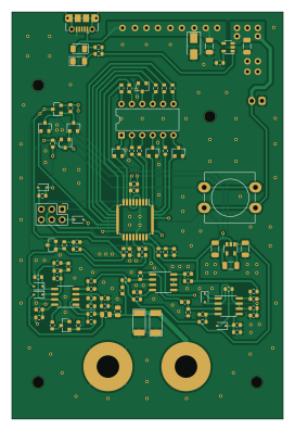
About the Esr meter PCB
Esr meter is an open source AVR/Arduino PCB design by vpatkov, published on GitHub. It is a 2-layer board measuring 66 × 99.1 mm, with 101 components from 43 distinct parts.
Its main chip is the ATMEGA88PA-AU, from the AVR/Arduino family. Other key parts include the MCP73831, TPS60403, TLV431, OPA1678 and QDSP-6064. By type, the board carries 44 resistors, 24 capacitors, 11 diodes, 9 transistors, 8 ICs and 4 connectors.
It belongs with the power & battery designs in this gallery.
From the project
AC ohmmeter
This device measures impedance at 100 kHz in assumption it's resistive[^1], basically an AC ohmmeter. Not for laboratory measurements, but for troubleshooting. The main usage is to find dried out electrolytic capacitors in aged electronics. Also may be used for continuity testing in a circuit containing inductors or transformers (it may be hard to distinguish a short from a winding at DC), or for finding shorted windings.
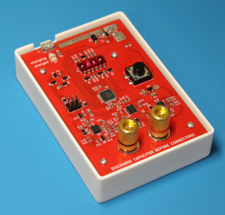
Main components on the Esr meter
Esr meter bill of materials (BOM)
101 components, 43 distinct parts — part numbers from the project's BOM.
| Qty | Part | Footprint | Refs |
|---|---|---|---|
| 1 | MCP73831 | SOT-23-5 | U1 |
| 1 | TPS60403 | SOT-23-5 | U2 |
| 1 | TLV431 | SOT-23 | U3 |
| 3 | OPA1678 | SO-8_3.9x4.9mm_P1.27mm | U4, U5, U8 |
| 1 | ATMEGA88PA-AU ATmega88PA-AU | TQFP-32_7x7mm_P0.8mm | U6 |
| 1 | QDSP-6064 | DIP-12_W7.62mm | U7 |
| 7 | DTC114E | SOT-23 | Q1, Q3, Q4, Q6, Q7, Q8, Q9 |
| 1 | IRLML6402 | SOT-23 | Q2 |
| 1 | MMBFJ113 | SOT-23 | Q5 |
| 1 | USB_B_Micro | USB_Micro-B_Molex-105017-0001 | J1 |
| 1 | JST-XH | JST_XH_S2B-XH-A-1_1x02_P2.50mm_Horizontal | J2 |
| 1 | Pin Header Male | PinHeader_2x03_P2.54mm_Vertical | J3 |
| 1 | Binding Post | BindingPost | J4 |
| 1 | SW_Push | SW_PUSH-12mm_Wuerth-430476085716 | SW1 |
| 1 | SMAJ5.0A | D_SMA | D1 |
| 1 | RED | LED_1206_3216Metric | D2 |
| 1 | GREEN | LED_1206_3216Metric | D3 |
| 5 | BAS316 | D_SOD-323 | D4, D5, D6, D7, D9 |
| 1 | BAT54J | D_SOD-323F | D8 |
| 2 | SM4007 | D_MELF | D10, D11 |
Show 23 more
| Qty | Part | Footprint | Refs |
|---|---|---|---|
| 2 | 4.7μ | C_1206_3216Metric | C1, C6 |
| 3 | 1μ | C_1206_3216Metric | C2, C4, C5 |
| 11 | 100N 100n | C_0603_1608Metric | C3, C8, C16, C17, C18, C19, C20, C21 +3 |
| 4 | 10N 10n | C_0603_1608Metric | C7, C9, C10, C15 |
| 1 | DNP | C_0603_1608Metric | C11 |
| 3 | 1n | C_0603_1608Metric | C12, C13, C14 |
| 3 | 33K 33k | R_0603_1608Metric | R1, R6, R22 |
| 1 | 3.3K 3.3k | R_0603_1608Metric | R2 |
| 2 | 3k | R_0603_1608Metric | R3, R4 |
| 5 | 10K 10k | R_0603_1608Metric | R5, R8, R9, R10, R18 |
| 1 | 31.6K 31.6k | R_0603_1608Metric | R7 |
| 1 | 100 | R_0603_1608Metric | R11 |
| 2 | 100K 100k | R_0603_1608Metric | R12, R13 |
| 5 | 1k | R_0603_1608Metric | R14, R15, R19, R26, R37 |
| 1 | DNP | R_0603_1608Metric | R16 |
| 2 | 1.58K 1.58k | R_0603_1608Metric | R17, R23 |
| 1 | 3.3M | R_0603_1608Metric | R20 |
| 1 | 2.2K 2.2k | R_0603_1608Metric | R21 |
| 1 | 499 | R_0805_2012Metric | R24 |
| 1 | 10 | R_0805_2012Metric | R25 |
| 8 | 2.4K 2.4k | R_0603_1608Metric | R27, R28, R29, R30, R31, R32, R33, R34 |
| 8 | 10 | R_0603_1608Metric | R35, R36, R38, R39, R41, R42, R43, R44 |
| 1 | 45.3K 45.3k | R_0603_1608Metric | R40 |
Esr meter design files
The KiCad project lives in the vpatkov/esr-meter repository on GitHub; these links point at the commit this page was built from.
- Layouthardware/esr-meter.kicad_pcb
- Schematichardware/esr-meter.kicad_sch
- BOMhardware/bom.csv
Esr meter: common questions
What microcontroller does the Esr meter use?
The Esr meter is built around the ATMEGA88PA-AU, from the AVR/Arduino family.
How big is the Esr meter PCB?
The Esr meter measures 66 × 99.1 mm, has 2 copper layers and is 1.6 mm thick.
How many components are on the Esr meter?
101 components, from 43 distinct parts, with part numbers taken from the project's own BOM. The full bill of materials is listed on this page.
Where can I download the Esr meter design files?
From the vpatkov/esr-meter repository on GitHub, which has the KiCad layout, the schematic and the BOM; the links under Design files point to each one.
Can I use the Esr meter design in my own project?
The repository has no license, so all rights stay with vpatkov. Use it as a reference, and ask the author before reusing the design.
Can I test firmware for the Esr meter without the hardware?
Yes. HardLabs builds a simulation of the board from its netlist and BOM, so you can run and debug AVR/Arduino firmware against it before you order a PCB.
Similar boards
 AVR/Arduino
V4
stuartpittaway
30 × 50 mm38 parts2LCC-BY-NC-4.01.1k AVR/Arduino
ModuleV450
30 × 61.4 mm39 parts2LCC-BY-NC-4.01.1k AVR/Arduino
Easyduino Atmega Nano
Hanqaqa
43.4 × 18 mm30 parts4LCERN-OHL-P-2.0746 AVR/Arduino
Easyduino Atmega
68.8 × 53.6 mm35 parts4LCERN-OHL-P-2.0746 AVR/Arduino
UsbGpib
xyphro
54 × 15 mm21 parts2LMIT683 AVR/Arduino
Lumberjack
peej
284.7 × 94.2 mm149 parts2LMIT402