
A500-USB-Keyboard-Adapter-RP2040

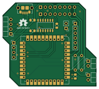
About the A500-USB-Keyboard-Adapter-RP2040 PCB
A500-USB-Keyboard-Adapter-RP2040 is an open source RP2040/RP2350 PCB design by wiretap-retro, published on GitHub. It is a 2-layer board measuring 48.8 × 43.9 mm, with 17 components from 14 distinct parts.
Its main chip is the RP2040_STAMP, from the RP2040/RP2350 family. Other key parts include the TXS0104ED. By type, the board carries 9 connectors, 4 resistors, 2 ICs and 2 capacitors.
It belongs with the keyboards and retro computing designs in this gallery.
From the project
A USB keyboard adapter for the Amiga 500 based on the Pi Stamp RP2040
Demo Video: https://youtu.be/7yw0AOvhLqg (Rev 0 board with bodges/resistors. These have been corrected and implemented in Rev 1.)
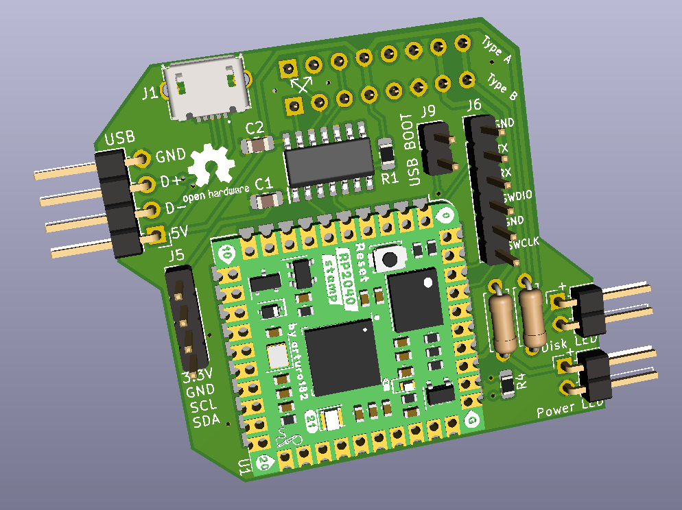
Main components on the A500-USB-Keyboard-Adapter-RP2040
A500-USB-Keyboard-Adapter-RP2040 bill of materials (BOM)
17 components, 14 distinct parts — part numbers from the project's BOM.
| Qty | Part | Footprint | Refs |
|---|---|---|---|
| 1 | TXS0104ED | SOIC127P600X175-14N | IC1 |
| 1 | RP2040_STAMP RP2040_Stamp | RP2040_Stamp_THT | U1 |
| 1 | USB3075-30-A | USB307530A | J1 |
| 1 | USB_HEADER | PinHeader_1x04_P2.54mm_Horizontal | J2 |
| 1 | Type A | PinSocket_1x08_P2.54mm_Vertical | J3 |
| 1 | Type B | PinSocket_1x08_P2.54mm_Vertical | J4 |
| 1 | I2C | PinHeader_1x04_P2.54mm_Vertical | J5 |
| 1 | DEBUG | PinHeader_1x06_P2.54mm_Vertical | J6 |
| 1 | Power LED | PinHeader_1x02_P2.54mm_Horizontal | J7 |
| 1 | Floppy LED | PinHeader_1x02_P2.54mm_Horizontal | J8 |
| 1 | USB_BOOT | PinHeader_1x02_P2.54mm_Vertical | J9 |
| 2 | 100NF 100nF | C_0805_2012Metric_Pad1.15x1.40mm_HandSolder | C1, C2 |
| 2 | 10K 10k | R_0805_2012Metric_Pad1.15x1.40mm_HandSolder | R1, R4 |
| 2 | R_Small | R_Axial_DIN0207_L6.3mm_D2.5mm_P7.62mm_Horizontal | R2, R3 |
A500-USB-Keyboard-Adapter-RP2040 design files
The KiCad project lives in the wiretap-retro/A500-USB-Keyboard-Adapter-RP2040 repository on GitHub; these links point at the commit this page was built from.
A500-USB-Keyboard-Adapter-RP2040: common questions
What microcontroller does the A500-USB-Keyboard-Adapter-RP2040 use?
The A500-USB-Keyboard-Adapter-RP2040 is built around the RP2040_STAMP, from the RP2040/RP2350 family.
How big is the A500-USB-Keyboard-Adapter-RP2040 PCB?
The A500-USB-Keyboard-Adapter-RP2040 measures 48.8 × 43.9 mm, has 2 copper layers and is 1.6 mm thick.
How many components are on the A500-USB-Keyboard-Adapter-RP2040?
17 components, from 14 distinct parts, with part numbers taken from the project's own BOM. The full bill of materials is listed on this page.
Where can I download the A500-USB-Keyboard-Adapter-RP2040 design files?
From the wiretap-retro/A500-USB-Keyboard-Adapter-RP2040 repository on GitHub, which has the KiCad layout and the BOM; the links under Design files point to each one.
Can I use the A500-USB-Keyboard-Adapter-RP2040 design in my own project?
The repository has no license, so all rights stay with wiretap-retro. Use it as a reference, and ask the author before reusing the design.
Can I test firmware for the A500-USB-Keyboard-Adapter-RP2040 without the hardware?
Yes. HardLabs builds a simulation of the board from its netlist and BOM, so you can run and debug RP2040/RP2350 firmware against it before you order a PCB.
Similar boards
 RP2040/RP2350
Open Book Abridged Edition
joeycastillo
85 × 115 mm29 parts2LCC-BY-SA-4.08.1k RP2040/RP2350
Corne
foostan
277.2 × 107.5 mm164 parts2LCC-BY-4.07.7k RP2040/RP2350
Corne
277.2 × 107.5 mm164 parts2LCC-BY-4.07.7k RP2040/RP2350
Msa
Mentra-Community
47.8 × 9.4 mm53 parts2LMIT1.2k RP2040/RP2350
Open Source Smart Glasses
93 × 10.5 mm80 parts4LMIT1.2k RP2040/RP2350
MSA
30.5 × 138 mm61 parts2LMIT1.2k