
Nixie alarm clock

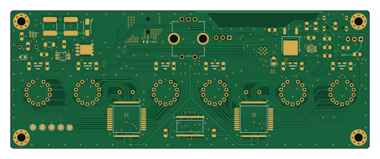
About the Nixie alarm clock PCB
Nixie alarm clock is an open source ESP32 PCB design by wojciechpaderewski, published on GitHub. It is a 2-layer board measuring 138 × 53 mm, with 115 components from 50 distinct parts.
Its main chip is the ESP32-S3-WROOM-1, from the ESP32 family. Other key parts include the LM3488MM, HV5530PG-G, TPS563219ADDFR, CD40109BQNSRQ1 and AP7363-33D-13. By type, the board carries 45 resistors, 30 capacitors, 8 ICs, 8 transistors, 6 diodes and 4 connectors.
It belongs with the iot & wireless and displays & leds designs in this gallery.
From the project
Home assistant integrated
Main components on the Nixie alarm clock
Nixie alarm clock bill of materials (BOM)
115 components, 50 distinct parts — part numbers from the project's BOM.
| Qty | Part | Footprint | Refs |
|---|---|---|---|
| 1 | LM3488MM | SOP65P490X110-8N | IC1 |
| 2 | HV5530PG-G | QFP80P1390X1390X235-44N | IC2, IC4 |
| 1 | TPS563219ADDFR | SOT65P280X110-8N | IC3 |
| 1 | CD40109BQNSRQ1 | SOIC127P780X200-16N | IC6 |
| 1 | AP7363-33D-13 | AP736333D13 | IC7 |
| 1 | MCP4018T-502E/LT MCP4018T-103E/LT | SOT65P210X110-6N | IC8 |
| 1 | ESP32-S3-WROOM-1 | ESP32-S3-WROOM-1 | U1 |
| 7 | DMN60H080DS-13 | SOT96P240X110-3N | Q1, Q2, Q3, Q4, Q5, Q6, Q7 |
| 1 | TPHR6503PL1,LQ TPH5200FNH,L1Q | TPHR6503PL1LQ | Q8 |
| 1 | PJ-094H-SMT-TR | PJ094HSMTTR | J1 |
| 1 | JST XH 2.54 3 pin | JST_XH_S3B-XH-A-1_1x03_P2.50mm_Horizontal | J2 |
| 1 | USB_C_RECEPTACLE_USB2.0_16P USB_C_Receptacle_USB2.0_16P | USB_C_Receptacle_GCT_USB4105-xx-A_16P_TopMnt_Horizontal | J3 |
| 1 | Goldpin 3pin | PinHeader_1x03_P2.54mm_Horizontal | J5 |
| 1 | RotaryEncoder_Switch | PEC12R41BBFS0012 | ENC1 |
| 1 | CEM-1203(42) CEM-1203_42_ | CEM-1203_42_ | LS1 |
| 6 | Z570M | Z570M | N1, N2, N3, N4, N5, N6 |
| 2 | 90V 0.3mA | neon_lamp | NE1, NE2 |
| 1 | SW_EN | B3U1000PM | SW1 |
| 1 | SW_GPIO0 | B3U1000PM | SW2 |
| 2 | PUSB3AB4Z | SON50P100X250X50-10N | D1, D3 |
Show 30 more
| Qty | Part | Footprint | Refs |
|---|---|---|---|
| 1 | ES1G | DIOM5227X260N | D2 |
| 1 | WE-TVS 824045812 | DFN-1610-2 | D4 |
| 1 | CDBUR0520 | D_0603_1608Metric_Pad1.05x0.95mm_HandSolder | D5 |
| 1 | 3.6V | D_0805_2012Metric_Pad1.15x1.40mm_HandSolder | D6 |
| 1 | SRP5030CA-2R2M 2.2uH 9.7A | SRP5030CA4R7M | L1 |
| 1 | 74437529203331 180uH 0.9A 6.3mΩ | L_12x12mm_H6mm | L2 |
| 2 | 22uF 10V | C_0805_2012Metric_Pad1.18x1.45mm_HandSolder | C1, C29 |
| 2 | 2.2uF 250 V | C_2220_5750Metric_Pad1.97x5.40mm_HandSolder | C2, C23 |
| 18 | GRM033R71E101KA01J 100nF 25V | C_0805_2012Metric_Pad1.18x1.45mm_HandSolder | C3, C4, C5, C6, C7, C8, C9, C10 +10 |
| 1 | C0805C332K5RACTU 12pF 16V | C0805 | C11 |
| 1 | GRM033R71E101KA01J 220pF 50V | C_0805_2012Metric_Pad1.18x1.45mm_HandSolder | C12 |
| 1 | GRM033R71E101KA01J 10pF 25V | C_0805_2012Metric_Pad1.18x1.45mm_HandSolder | C13 |
| 2 | CL21A106KPFNNNE 10uF 10V | C_0805_2012Metric_Pad1.18x1.45mm_HandSolder | C17, C18 |
| 2 | TAJD107K016RNJ 100uF 16V | CAPPM7344X310N | C20, C21 |
| 1 | GRM033R71E101KA01J 10nF 25V | C_0805_2012Metric_Pad1.18x1.45mm_HandSolder | C27 |
| 1 | ERJ-UP6D5101V 56kΩ | R_0805_2012Metric_Pad1.20x1.40mm_HandSolder | R1 |
| 1 | ERJ-UP6D5101V 10kΩ | R_0805_2012Metric_Pad1.20x1.40mm_HandSolder | R2 |
| 4 | ERJ-UP6D5101V 5.1kΩ | R_0805_2012Metric_Pad1.20x1.40mm_HandSolder | R3, R4, R42, R43 |
| 1 | CRCW04022K74FKED 0Ω | R_0805_2012Metric_Pad1.20x1.40mm_HandSolder | R5 |
| 1 | ERJ-UP6D5101V 100Ω | R_0805_2012Metric_Pad1.20x1.40mm_HandSolder | R6 |
| 15 | ERJ-UP6D5101V 10k | R_0805_2012Metric_Pad1.20x1.40mm_HandSolder | R7, R8, R9, R17, R18, R19, R20, R24 +7 |
| 2 | CRCW04022K74FKED 1MΩ | R_1206_3216Metric_Pad1.30x1.75mm_HandSolder | R10, R15 |
| 1 | CRCW04022K74FKED 14.3kΩ | R_0805_2012Metric_Pad1.20x1.40mm_HandSolder | R11 |
| 1 | CRCW04022K74FKED 2.49MΩ | R_1206_3216Metric_Pad1.30x1.75mm_HandSolder | R12 |
| 1 | CRCW04022K74FKED 100Ω | R_0805_2012Metric_Pad1.20x1.40mm_HandSolder | R13 |
| 1 | ERJ-UP6D5101V 75mΩ | R_0805_2012Metric_Pad1.20x1.40mm_HandSolder | R14 |
| 1 | CRCW04022K74FKED 10kΩ | R_0805_2012Metric_Pad1.20x1.40mm_HandSolder | R16 |
| 2 | RK73H2ATTE1003F 390kΩ 1/2W | R_0805_2012Metric_Pad1.20x1.40mm_HandSolder | R21, R27 |
| 7 | RK73H2ATTE1003F 35.7kΩ | R_0805_2012Metric_Pad1.20x1.40mm_HandSolder | R22, R23, R25, R28, R31, R33, R44 |
| 6 | RK73H2ATTE1003F 51kΩ | R_0805_2012Metric_Pad1.20x1.40mm_HandSolder | R36, R37, R38, R39, R40, R41 |
Nixie alarm clock design files
The KiCad project lives in the wojciechpaderewski/Nixie_alarm_clock repository on GitHub; these links point at the commit this page was built from.
Nixie alarm clock: common questions
What microcontroller does the Nixie alarm clock use?
The Nixie alarm clock is built around the ESP32-S3-WROOM-1, from the ESP32 family.
How big is the Nixie alarm clock PCB?
The Nixie alarm clock measures 138 × 53 mm, has 2 copper layers and is 1.6 mm thick.
How many components are on the Nixie alarm clock?
115 components, from 50 distinct parts, with part numbers taken from the project's own BOM. The full bill of materials is listed on this page.
Where can I download the Nixie alarm clock design files?
From the wojciechpaderewski/Nixie_alarm_clock repository on GitHub, which has the KiCad layout, the schematic and the BOM; the links under Design files point to each one.
Can I use the Nixie alarm clock design in my own project?
The repository has no license, so all rights stay with wojciechpaderewski. Use it as a reference, and ask the author before reusing the design.
Can I test firmware for the Nixie alarm clock without the hardware?
Yes. HardLabs builds a simulation of the board from its netlist and BOM, so you can run and debug ESP32 firmware against it before you order a PCB.
Similar boards
 ESP32
ESP32Open Book Abridged Edition
joeycastillo
85 × 115 mm65 parts2LCC-BY-SA-4.08.1k ESP32
ESP32Esp32 minimal
atopile
36.2 × 26.8 mm20 parts2LMIT4.0k ESP32
ESP32Badge
56.3 × 39 mm239 parts4LMIT4.0k ESP32
ESP32Controller
StuckAtPrototype
29 × 74 mm58 parts4LApache-2.03.8k ESP32
ESP32Racer
36 × 50.2 mm70 parts4LApache-2.03.8k ESP32
ESP32Bitaxe
skot
56.5 × 99.8 mm86 parts4LCERN-OHL-S-2.01.4k