
Schaltung labor netzteil display

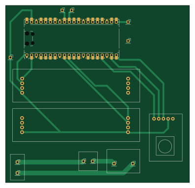
About the Schaltung labor netzteil display PCB
Schaltung labor netzteil display is an open source RP2040/RP2350 PCB design by YannickKoenig, published on GitHub under the MIT license. It is a 2-layer board measuring 99.1 × 95.3 mm, with 15 components from 14 distinct parts.
Its main chip is the RaspberryPi_Pico, from the RP2040/RP2350 family. By type, the board carries 11 connectors, 3 ICs and 1 module.
It belongs with the power & battery, displays & leds and test & measurement designs in this gallery.
From the project
A simple, microcontroller-based PWM buck converter power supply, designed to provide precise voltage control and current measurement.
4. Connect the wiring: - Connect the Buck Converter PCB and the Frontend PCB (if used) using the following connections:
- Connect the output of the Buck Converter:
- Vout+` → Positive output terminal (e.g., banana plug).
- Vout-` → Negative output terminal (e.g., banana plug).
You can use banana plugs, terminal blocks, or any other suitable connectors for your output.
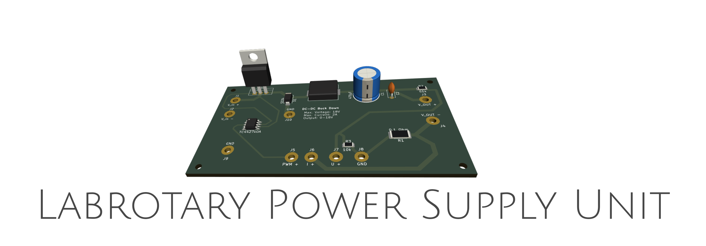
Main components on the Schaltung labor netzteil display
Schaltung labor netzteil display bill of materials (BOM)
15 components, 14 distinct parts.
| Qty | Part | Footprint | Refs |
|---|---|---|---|
| 2 | ~ | TM1637 | U1, U2 |
| 1 | ~ | KY_40 | U3 |
| 1 | RaspberryPi_Pico | RaspberryPi_Pico_Common_Unspecified | A1 |
| 1 | V_psu + | PinSocket_1x01_P2.54mm_Vertical | J1 |
| 1 | V_psu - | PinSocket_1x01_P2.54mm_Vertical | J2 |
| 1 | V_out + | PinSocket_1x01_P2.54mm_Vertical | J3 |
| 1 | V_out - | PinSocket_1x01_P2.54mm_Vertical | J4 |
| 1 | V_in + | PinSocket_1x01_P2.54mm_Vertical | J5 |
| 1 | V_in - | PinSocket_1x01_P2.54mm_Vertical | J6 |
| 1 | PWM | PinSocket_1x01_P2.54mm_Vertical | J7 |
| 1 | U_in | PinSocket_1x01_P2.54mm_Vertical | J8 |
| 1 | I_in | PinSocket_1x01_P2.54mm_Vertical | J9 |
| 1 | SW+ | PinSocket_1x01_P2.54mm_Vertical | J10 |
| 1 | SW- | PinSocket_1x01_P2.54mm_Vertical | J11 |
Schaltung labor netzteil display design files
The KiCad project lives in the YannickKoenig/DIY-Laboratory-Power-Supply repository on GitHub; these links point at the commit this page was built from.
Schaltung labor netzteil display: common questions
What microcontroller does the Schaltung labor netzteil display use?
The Schaltung labor netzteil display is built around the RaspberryPi_Pico, from the RP2040/RP2350 family.
How big is the Schaltung labor netzteil display PCB?
The Schaltung labor netzteil display measures 99.1 × 95.3 mm, has 2 copper layers and is 1.6 mm thick.
How many components are on the Schaltung labor netzteil display?
15 components, from 14 distinct parts. The full bill of materials is listed on this page.
Where can I download the Schaltung labor netzteil display design files?
From the YannickKoenig/DIY-Laboratory-Power-Supply repository on GitHub, which has the KiCad layout and the schematic; the links under Design files point to each one.
Can I use the Schaltung labor netzteil display design in my own project?
Yes, under the terms of its MIT license, which YannickKoenig chose for the repository.
Can I test firmware for the Schaltung labor netzteil display without the hardware?
Yes. HardLabs builds a simulation of the board from its netlist and BOM, so you can run and debug RP2040/RP2350 firmware against it before you order a PCB.
More boards in DIY-Laboratory-Power-Supply
Similar boards
 RP2040/RP2350
OSO-BOOK-C1
joeycastillo
85 × 115 mm29 parts2LCC-BY-SA-4.08.1k RP2040/RP2350
Corne chocolate
foostan
277.2 × 107.5 mm164 parts2LCC-BY-4.07.7k RP2040/RP2350
Corne cherry
277.2 × 107.5 mm164 parts2LCC-BY-4.07.7k RP2040/RP2350
LogicAnalyzer
gusmanb
57 × 55.2 mm6 parts2LGPL-3.05.0k RP2040/RP2350
Jitx design
55.5 × 65 mm26 parts4LGPL-3.05.0k RP2040/RP2350
Main
google
98 × 71 mm102 parts2LApache-2.02.9k