
Mission mimosa

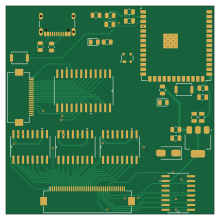
About the Mission mimosa PCB
Mission mimosa is an open source ESP32 PCB design by zademahi238, published on GitHub. It is a 2-layer board measuring 55 × 55 mm, with 31 components from 19 distinct parts.
Its main chip is the ESP32-S3-WROOM-2, from the ESP32 family. Other key parts include the SN74HC595NSR, AMS1117-3.3 and CD74HC4067M96. By type, the board carries 8 capacitors, 7 ICs, 7 resistors, 4 diodes, 3 connectors and 2 switches.
From the project
Mission Mimosa explores visuo-tactile manipulation on the SO-101 robotic arm, combining visual observations with tactile sensing for robot manipulation.
Mission Mimosa explores visuo-tactile manipulation on the SO-101 robotic arm, combining visual observations with tactile sensing for robot manipulation.
To answer this, we compare task-completion success rates with and without tactile sensing across different robot-learning policies.
The SO-101 robotic arm is used as the primary platform for collecting demonstrations and evaluating learned manipulation policies.
Main components on the Mission mimosa
Mission mimosa bill of materials (BOM)
31 components, 19 distinct parts.
| Qty | Part | Footprint | Refs |
|---|---|---|---|
| 4 | SN74HC595NSR | NS16 | U1, U3, U4, U8 |
| 1 | ESP32-S3-WROOM-2 | ESP32-S3-WROOM-1 | U2 |
| 1 | AMS1117-3.3 | SOT-223-3_TabPin2 | U5 |
| 1 | CD74HC4067M96 | DW24 | U7 |
| 1 | SFV20R-2STE1HLF | Hirose_FH12-20S-0.5SH_1x20-1MP_P0.50mm_Horizontal | J2 |
| 1 | 62684-402100ALF | Hirose_FH12-40S-0.5SH_1x40-1MP_P0.50mm_Horizontal | J3 |
| 1 | USB_C_Receptacle_USB2.0_16P | USB_C_Receptacle_GCT_USB4105-xx-A_16P_TopMnt_Horizontal | J5 |
| 1 | RESET | SW_Push_SPST_NO_Alps_SKRK | SW1 |
| 1 | BOOT | SW_Push_SPST_NO_Alps_SKRK | SW2 |
| 1 | SP0503BAHT | SOT-143 | D7 |
| 2 | LED | LED_0805_2012Metric | D15, D16 |
| 1 | SS14 | D_SMA | D17 |
| 5 | 0.1uF | C_0805_2012Metric | C4, C5, C7, C15, C17 |
| 2 | 10uF | C_0805_2012Metric | C6, C14 |
| 1 | 22uF | C_0805_2012Metric | C16 |
| 1 | 20K | R_0805_2012Metric | R1 |
| 2 | 5.1K | R_0805_2012Metric | R6, R8 |
| 2 | 10K | R_0805_2012Metric | R7, R20 |
| 2 | 330R | R_0805_2012Metric | R17, R18 |
Mission mimosa design files
The KiCad project lives in the zademahi238/mission-mimosa repository on GitHub; these links point at the commit this page was built from.
- Layoutpcb/Readout_BoardV2.kicad_pcb
- Schematicpcb/Readout_BoardV2.kicad_sch
Mission mimosa: common questions
What microcontroller does the Mission mimosa use?
The Mission mimosa is built around the ESP32-S3-WROOM-2, from the ESP32 family.
How big is the Mission mimosa PCB?
The Mission mimosa measures 55 × 55 mm, has 2 copper layers and is 1.6 mm thick.
How many components are on the Mission mimosa?
31 components, from 19 distinct parts. The full bill of materials is listed on this page.
Where can I download the Mission mimosa design files?
From the zademahi238/mission-mimosa repository on GitHub, which has the KiCad layout and the schematic; the links under Design files point to each one.
Can I use the Mission mimosa design in my own project?
The repository has no license, so all rights stay with zademahi238. Use it as a reference, and ask the author before reusing the design.
Can I test firmware for the Mission mimosa without the hardware?
Yes. HardLabs builds a simulation of the board from its netlist and BOM, so you can run and debug ESP32 firmware against it before you order a PCB.
Earlier revisions in the repo: Readout_BoardV1
Similar boards
 ESP32
OSO-BOOK-B1
joeycastillo
85 × 115 mm65 parts2LCC-BY-SA-4.08.1k ESP32
Powertrain
byrantech
64 × 45.4 mm171 parts4LMIT4.3k ESP32
Esp32 minimal
atopile
36.2 × 26.8 mm20 parts2LMIT4.0k ESP32
Badge
56.3 × 39 mm239 parts4LMIT4.0k ESP32
Racer
StuckAtPrototype
36 × 50.2 mm70 parts4LApache-2.03.8k ESP32
Controller
29 × 74 mm58 parts4LApache-2.03.8k