
Mixed signal sensor interface

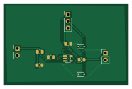
About the Mixed signal sensor interface PCB
Mixed signal sensor interface is an open source PCB design by zeyadeldokmak, published on GitHub. It is a 2-layer board measuring 46.5 × 30.5 mm, with 11 components from 10 distinct parts.
Other key parts include the MCP6001-OT. By type, the board carries 3 connectors, 3 resistors, 2 diodes, 2 capacitors and 1 IC.
It belongs with the sensors designs in this gallery.
From the project
LTspice and KiCad design of a mixed-signal sensor interface for a 3.3 V ADC.
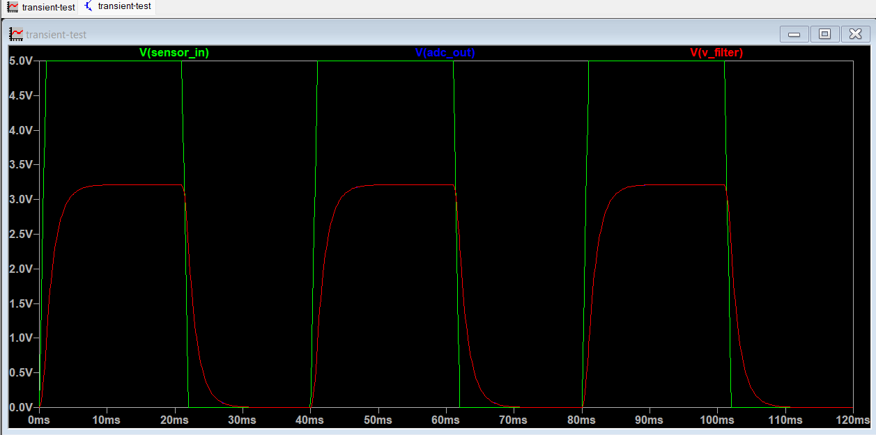
A simulated mixed-signal interface that conditions a 0–5 V sensor signal for a 3.3 V microcontroller ADC. The project combines analogue circuit simulation in LTspice with schematic capture, PCB layout and manufacturing-output generation in KiCad.
The circuit performs four main functions:
1. Scales the 0–5 V sensor input to approximately 0–3.214 V. 2. Applies first-order low-pass filtering. 3. Buffers the conditioned signal using an MCP6001 operational amplifier. 4. Protects the ADC input using a 1 kΩ series resistor and BAT54WS Schottky clamp diodes.
Main components on the Mixed signal sensor interface
Mixed signal sensor interface bill of materials (BOM)
11 components, 10 distinct parts — part numbers from the project's BOM.
| Qty | Part | Footprint | Refs |
|---|---|---|---|
| 1 | MCP6001-OT | SOT-23-5 | U1 |
| 1 | SENSOR_INPUT | PinHeader_1x02_P2.54mm_Vertical | J1 |
| 1 | POWER_INPUT | PinHeader_1x03_P2.54mm_Vertical | J2 |
| 1 | ADC_OUTPUT | PinHeader_1x02_P2.54mm_Vertical | J3 |
| 2 | BAT54WS | D_SOD-323 | D1, D2 |
| 1 | 220NF 220nF | C_0805_2012Metric | C1 |
| 1 | 100NF 100nF | C_0805_2012Metric | C2 |
| 1 | 10K 10k | R_0805_2012Metric | R1 |
| 1 | 18K 18k | R_0805_2012Metric | R2 |
| 1 | 1k | R_0805_2012Metric | R3 |
Mixed signal sensor interface design files
The KiCad project lives in the zeyadeldokmak/mixed-signal-sensor-interface-pcb repository on GitHub; these links point at the commit this page was built from.
Mixed signal sensor interface: common questions
How big is the Mixed signal sensor interface PCB?
The Mixed signal sensor interface measures 46.5 × 30.5 mm, has 2 copper layers and is 1.6 mm thick.
How many components are on the Mixed signal sensor interface?
11 components, from 10 distinct parts, with part numbers taken from the project's own BOM. The full bill of materials is listed on this page.
Where can I download the Mixed signal sensor interface design files?
From the zeyadeldokmak/mixed-signal-sensor-interface-pcb repository on GitHub, which has the KiCad layout, the schematic and the BOM; the links under Design files point to each one.
Can I use the Mixed signal sensor interface design in my own project?
The repository has no license, so all rights stay with zeyadeldokmak. Use it as a reference, and ask the author before reusing the design.
Similar boards

Sensor smd
scottbez1
40 × 20 mm5 parts2LApache-2.04.2k
Sensors
StuckAtPrototype
15.2 × 9 mm14 parts4LApache-2.03.8k
Microphone
Mentra-Community
5.5 × 6.1 mm6 parts2LMIT1.2k
TemperaturePCB PANEL
stuartpittaway
116 × 75.5 mm178 parts2LCC-BY-NC-4.01.1k
Pots
shanteacontrols
390 × 93 mm75 parts2LApache-2.0956
ButtonsLEDs
390 × 37 mm82 parts2LApache-2.0956