
31 open source boards using the MCP6001-OT
Real designs built with the MCP6001-OT, from public GitHub projects: a quick way to see how others power, decouple and connect it. Each board comes with its KiCad files, full parts list and a render — and you can simulate its firmware on HardLabs.
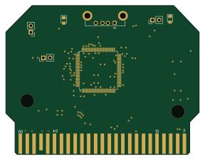 RISC-V
RISKYMSX
arkadiuszmakarenko
71.9 × 55.5 mm37 parts4LNo license22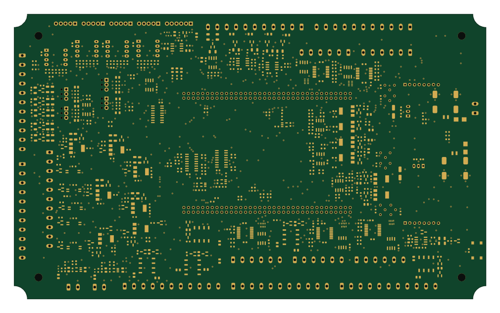
CTA control board
PySpice-org
252 × 152 mm614 parts4LNo license9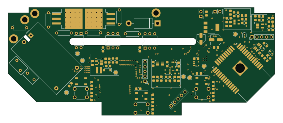 ESP32
SenseEHajo
ehajo
141 × 56.9 mm97 parts2LNo license5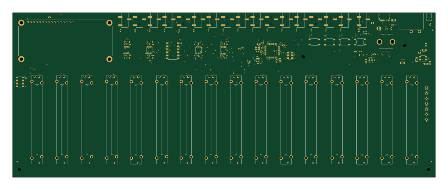 STM32
Faderbay
vonmartins
360 × 140 mm174 parts4LNo license4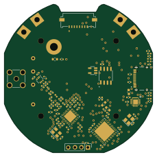 STM32
ArmLabRadio
explosion33
57.2 × 57.2 mm90 parts2LNo license4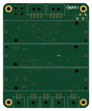 STM32
Power board
tudsat-rocket
78 × 95 mm142 parts4LNo license3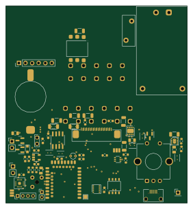
Control
Jochen0x90h
70 × 76 mm78 parts2LCC-BY-NC-4.03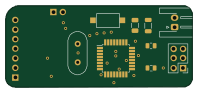 AVR/Arduino
I protect2.0
PsVenom
49.5 × 21.6 mm30 parts4LNo license2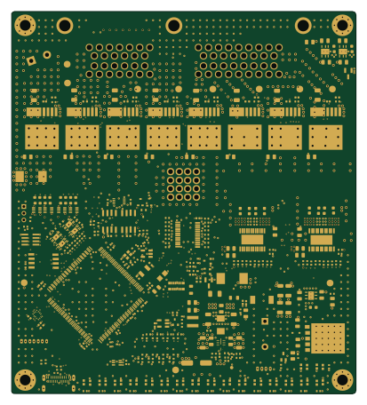 STM32
Pdms
PGRacing
102.5 × 113.8 mm473 parts4LNo license1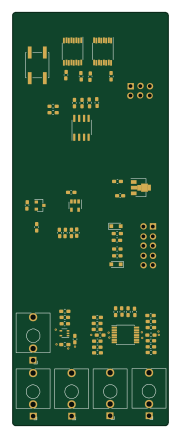 AVR/Arduino
Multi vu eurorack
jjradler
41.3 × 109.5 mm130 parts2LCC0-1.01- schematic only · 49 partsESP32
ATX-24-Pin-Inline-Power-Monitoring-Board
KazmirFahrier
49 partsMIT1 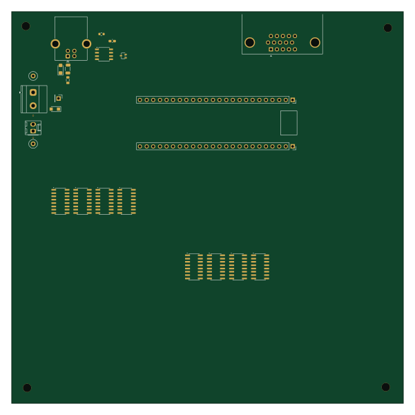
Gatebench
alheir
150 × 150 mm305 parts4LCERN-OHL-P-2.00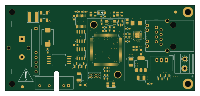 STM32
ETH1ISO224
BehrensG
100 × 45 mm137 parts4LNo license0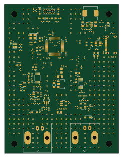 STM32
Mixed-Signal STM32
cipher8-0
60.1 × 78 mm110 parts4LNo license0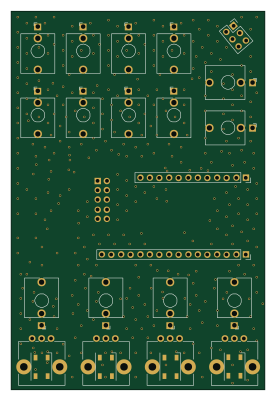
Hekla
WiggisModular
67 × 100 mm101 parts2LNo license0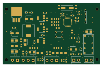 STM32
PUTM EV APPS 2021
PUT-Motorsport
100.7 × 63.5 mm72 parts2LApache-2.00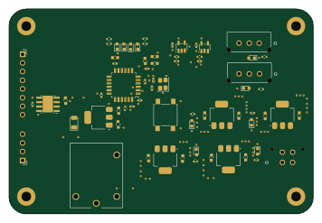 STM32
FSNS-APPS-2025
nedrg0
89 × 60 mm69 parts2LMIT0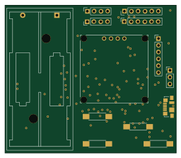 STM32
LCRmeter
ironiron
64 × 55.3 mm68 parts2LMIT0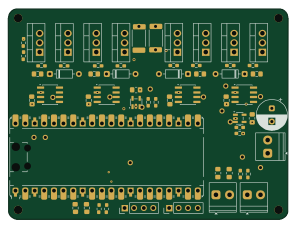 RP2040/RP2350
HBridge
serpentsniper
74 × 55.8 mm59 parts2LMIT0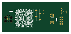
Tc5
mdeweerd
59.2 × 26.6 mm13 parts2LNo license0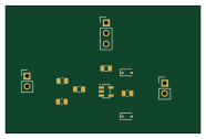
Mixed signal sensor interface
zeyadeldokmak
46.5 × 30.5 mm11 parts2LNo license0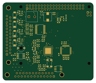
Flight computer
Purdue-Space-Program
78 × 67 mm102 parts4LNo license2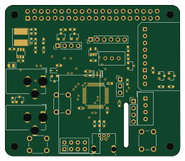 STM32
TITAN Board
hpvdt
65 × 56 mm58 parts2LNo license1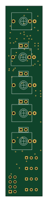
Expander1 V1.0
VoltageFoundryMod
19 × 99 mm50 parts2LGPL-3.01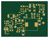
PWR Control
Heorenmaru
39.9 × 30.6 mm45 parts2LCC-BY-SA-4.01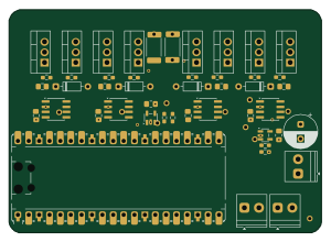 RP2040/RP2350
HBridge backup1
75 × 53.8 mm47 parts2LMIT0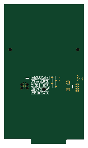
Tc7
70.6 × 123.5 mm13 parts2LNo license0 AVR/Arduino
Controller
kuellenberg
213 × 24 mm82 parts2LNo license0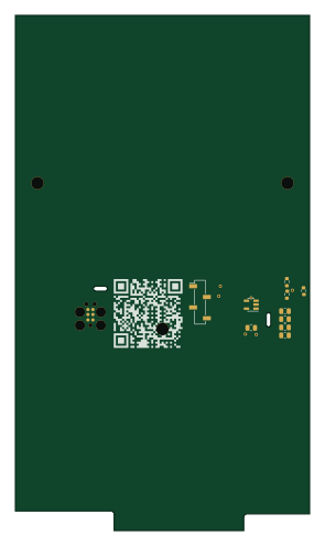
Tc8
70.6 × 123.5 mm13 parts2LNo license0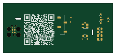
Tc6
59.2 × 26.6 mm12 parts2LNo license0
BatteryAmp
SJSURoboticsTeam
41 × 13 mm11 parts2LNo license1
How designs wire the MCP6001-OT
Read from the KiCad layouts of 26 open source designs, one per repository: what each pin of the MCP6001-OT connects to, and the resistors, capacitors and other passives placed on it.
- Pin 1 has a series resistor on 21 of 26 designs, most often 10 kΩ (then 100 Ω).
- The - pin has a series resistor on 20 of 26 designs, most often 10 kΩ (then 100 kΩ).
- The V- pin is tied to GND on 22 of 26 designs (5V on 2, a signal on 2).
- The V+ pin has a decoupling capacitor on 15 of 26 designs, most often 100 nF (then 1 µF).
| Pin | Connected to | Parts on the pin |
|---|---|---|
| Pin 1 | Connected to: Signal 100% |
|
| V-pin 2 | Connected to: GND 85% | — |
| +pin 3 | Connected to: Signal 81% · GND 15% |
|
| -pin 4 | Connected to: Signal 100% |
|
| V+pin 5 | Connected to: 3.3V 81% |
|
Connections count pins, parts count designs; values in brackets are how many parts had that value. Designs read include RISKYMSX by arkadiuszmakarenko, CTA control board by PySpice-org, SenseEHajo by ehajo and ArmLabRadio PCB by explosion33.
The MCP6001-OT in open source designs
The gallery holds 31 open source boards using the MCP6001-OT from 27 GitHub repositories; a typical one measures about 70.6 × 58.6 mm and carries around 69 components.
67% are two-layer designs, the rest use four layers or more, and 32% carry an open source license.
The most starred is RISKYMSX by arkadiuszmakarenko.
Parts used alongside the MCP6001-OT
Microcontrollers on boards using the MCP6001-OT
What boards using the MCP6001-OT are built for
MCP6001-OT: common questions
Where can I find a MCP6001-OT reference design?
Each of the 31 boards on this page is a real design using the MCP6001-OT. Open one to see how it is wired up, with the full BOM, a render of the layout and links to its KiCad files.
What resistor goes on the MCP6001-OT pin 1?
Pin 1 has a series resistor on 21 of 26 designs, most often 10 kΩ (then 100 Ω). Counted from the KiCad layouts of 26 open source designs using the MCP6001-OT.
What resistor goes on the MCP6001-OT - pin?
The - pin has a series resistor on 20 of 26 designs, most often 10 kΩ (then 100 kΩ). Counted from the KiCad layouts of 26 open source designs using the MCP6001-OT.
How is the MCP6001-OT V- pin connected?
The V- pin is tied to GND on 22 of 26 designs (5V on 2, a signal on 2). Counted from the KiCad layouts of 26 open source designs using the MCP6001-OT.
What parts are used alongside the MCP6001-OT?
The USBLC6-2SC6, AP2112K-3.3, DS3231M, LM1117-3.3 and MCP6004 appear in the most repositories here.
Which microcontrollers do boards using the MCP6001-OT use?
Most are built on STM32 (10), AVR/Arduino (3), ESP32 (2) and RP2040/RP2350 (2).
How big is a typical board using the MCP6001-OT?
The median is 70.6 × 58.6 mm, and 67% are two-layer designs.
What is the most popular open source board using the MCP6001-OT?
By GitHub stars, RISKYMSX by arkadiuszmakarenko, with 22 stars.
Can I simulate one of these boards using the MCP6001-OT before building it?
Yes. HardLabs turns a board's netlist and BOM into a working simulation, so you can boot and test firmware against it with no hardware on your desk.