
InduLink-485

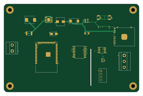
About the InduLink-485 PCB
InduLink-485 is an open source ESP32 PCB design by 8aChristian, published on GitHub under the MIT license. It is a 4-layer board measuring 115 × 75 mm, with 20 components from 19 distinct parts.
Its main chip is the ESP32-S3-WROOM-1-N8R8, from the ESP32 family. Other key parts include the SIM7080G, LMR14030SDDAR, AP2112K-3.3TRG1, ISO7721DWR and B0505S-1WR3. By type, the board carries 7 ICs, 5 diodes, 4 connectors, 2 capacitors, 1 fuse and 1 inductor.
It belongs with the iot & wireless designs in this gallery.
From the project
InduLink-485 is a rugged, industrial-grade IoT gateway and telemetry edge node designed for mission-critical industrial automation, SCADA networks, PLC monitoring, and remote field deployments. Built around the high-performance Espressif ESP32-S3 dual-core microcontroller and the
InduLink-485 is a rugged, industrial-grade IoT gateway and telemetry edge node designed for mission-critical industrial automation, SCADA networks, PLC monitoring, and remote field deployments. Built around the high-performance Espressif ESP32-S3 dual-core microcontroller and the SIMCom SIM7080G multi-band cellular modem, it delivers robust, isolated bidirectional RS-485 / Modbus RTU communication with dual-link connectivity over global LTE-M, NB-IoT, Wi-Fi, and Bluetooth Low Energy.
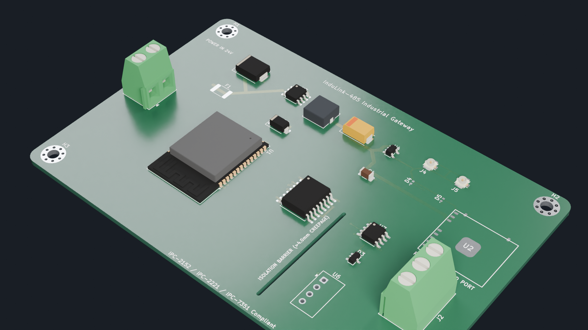
Main components on the InduLink-485
InduLink-485 bill of materials (BOM)
20 components, 19 distinct parts — part numbers from the project's BOM.
| Qty | Part | Footprint | Refs |
|---|---|---|---|
| 1 | ESP32-S3-WROOM-1-N8R8 Espressif Systems | ESP32-S3-WROOM-1 | U1 |
| 1 | SIM7080G SIMCom Wireless | SIMCom_SIM7080G | U2 |
| 1 | LMR14030SDDAR Texas Instruments | SOIC-8-1EP_3.9x4.9mm_P1.27mm_EP2.29x3mm | U3 |
| 1 | AP2112K-3.3TRG1 Diodes Incorporated | SOT-23-5 | U4 |
| 1 | ISO7721DWR Texas Instruments | SOIC-16W_7.5x10.3mm_P1.27mm | U5 |
| 1 | B0505S-1WR3 Mornsun | Converter_DCDC_TRACO_TME_03xxS_05xxS_12xxS_Single_THT | U6 |
| 1 | MAX13487EESA+ Analog Devices / Maxim | SOIC-8_3.9x4.9mm_P1.27mm | U7 |
| 1 | 1715721 MKDS_1.5_2_5.08 Phoenix Contact | TerminalBlock_Phoenix_MKDS-1,5-2-5.08_1x02_P5.08mm_Horizontal | J1 |
| 1 | 1715734 RS485_PORT Phoenix Contact | TerminalBlock_Phoenix_MKDS-1,5-3-5.08_1x03_P5.08mm_Horizontal | J2 |
| 1 | U.FL-R-SMT-1 LTE_U.FL Hirose Electric | U.FL_Hirose_U.FL-R-SMT-1_Vertical | J4 |
| 1 | U.FL-R-SMT-1 GNSS_U.FL Hirose Electric | U.FL_Hirose_U.FL-R-SMT-1_Vertical | J5 |
| 1 | MF-MSMF075-2 Bourns | Fuse_1812_4532Metric | F1 |
| 1 | SMCJ33CA Littelfuse / Vishay | D_SMC | D1 |
| 1 | B240A-13-F B240A Diodes Incorporated | D_SMA | D2 |
| 1 | SM712.TCT Semtech | SOT-23 | D3 |
| 2 | CD0402-T05C Bourns | D_0402_1005Metric | D4, D5 |
| 1 | 744314101 10uH_3.5A Wurth Elektronik | L_Wuerth_HCI-7030 | L1 |
| 1 | 6TPB1000M 1000uF_6.3V_POSCAP Panasonic | CP_EIA-7343-31_Kemet-D | C3 |
| 1 | GRM31CR61A107ME15L 100uF_10V Murata / TDK | C_1206_3216Metric | C4 |
InduLink-485 design files
The KiCad project lives in the 8aChristian/InduLink-485 repository on GitHub; these links point at the commit this page was built from.
InduLink-485: common questions
What microcontroller does the InduLink-485 use?
The InduLink-485 is built around the ESP32-S3-WROOM-1-N8R8, from the ESP32 family.
How big is the InduLink-485 PCB?
The InduLink-485 measures 115 × 75 mm, has 4 copper layers and is 1.6 mm thick.
How many components are on the InduLink-485?
20 components, from 19 distinct parts, with part numbers taken from the project's own BOM. The full bill of materials is listed on this page.
Where can I download the InduLink-485 design files?
From the 8aChristian/InduLink-485 repository on GitHub, which has the KiCad layout, the schematic and the BOM; the links under Design files point to each one.
Can I use the InduLink-485 design in my own project?
Yes, under the terms of its MIT license, which 8aChristian chose for the repository.
Can I test firmware for the InduLink-485 without the hardware?
Yes. HardLabs builds a simulation of the board from its netlist and BOM, so you can run and debug ESP32 firmware against it before you order a PCB.
Similar boards
 ESP32
ESP32Open Book Abridged Edition
joeycastillo
85 × 115 mm65 parts2LCC-BY-SA-4.08.1k ESP32
ESP32Badge
atopile
56.3 × 39 mm239 parts4LMIT4.0k ESP32
ESP32Esp32 minimal
36.2 × 26.8 mm20 parts2LMIT4.0k ESP32
ESP32Racer
StuckAtPrototype
36 × 50.2 mm70 parts4LApache-2.03.8k ESP32
ESP32Controller
29 × 74 mm58 parts4LApache-2.03.8k ESP32
ESP32Bitaxe
skot
56.5 × 99.8 mm86 parts4LCERN-OHL-S-2.01.4k