
SmartPetCollar

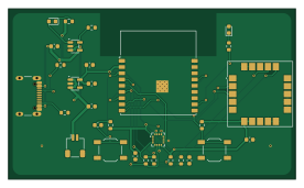
About the SmartPetCollar PCB
SmartPetCollar is an open source ESP32 PCB design by 8aChristian, published on GitHub under the MIT license. It is a 2-layer board measuring 69 × 41 mm, with 30 components from 22 distinct parts.
Its main chip is the ESP32-C3-WROOM-02-N4, from the ESP32 family. Other key parts include the MCP73831T-2ACI/OT, AP2112K-3.3TRG1, LIS3DH and SAM-M8Q-0-10. By type, the board carries 10 resistors, 8 capacitors, 5 ICs, 2 connectors, 2 switches and 2 diodes.
It belongs with the iot & wireless, rf & radio and wearables designs in this gallery.
From the project
SmartPet es una solución de hardware embebido de grado industrial para collares inteligentes de mascotas (pet wearables). Diseñado en KiCad 10, integra procesamiento ultrarrápido con conectividad Wi-Fi / Bluetooth Low Energy (BLE), posicionamiento satelital GNSS/GPS con antena de
SmartPet es una solución de hardware embebido de grado industrial para collares inteligentes de mascotas (pet wearables). Diseñado en KiCad 10, integra procesamiento ultrarrápido con conectividad Wi-Fi / Bluetooth Low Energy (BLE), posicionamiento satelital GNSS/GPS con antena de parche integrada, sensores de actividad e inclinación triaxial (IMU), medición de temperatura corporal (NTC) y un sistema completo de gestión de batería LiPo con recarga USB-C.
Main components on the SmartPetCollar
SmartPetCollar bill of materials (BOM)
30 components, 22 distinct parts — part numbers from the project's BOM.
| Qty | Part | Footprint | Refs |
|---|---|---|---|
| 1 | ESP32-C3-WROOM-02-N4 Espressif | ESP32-C3-WROOM-02 | U1 |
| 1 | MCP73831T-2ACI/OT Microchip | SOT-23-5 | U2 |
| 1 | AP2112K-3.3TRG1 Diodes Incorporated | SOT-23-5 | U3 |
| 1 | LIS3DH STMicroelectronics | LGA-16_3x3mm_P0.5mm | U4 |
| 1 | SAM-M8Q-0-10 SAM-M8Q u-blox | ublox_SAM-M8Q | U5 |
| 1 | SM02B-SRSS-TB BATT_1S JST | JST_SH_SM02B-SRSS-TB_1x02-1MP_P1.00mm_Horizontal | J1 |
| 1 | USB4105-GF-A USB-C GCT | USB_C_Receptacle_GCT_USB4105-xx-A_16P_TopMnt_Horizontal | J2 |
| 1 | TL3342F160QG RESET E-Switch | SW_SPST_TL3342 | SW1 |
| 1 | TL3342F160QG BOOT E-Switch | SW_SPST_TL3342 | SW2 |
| 1 | NCP18XH103J03RB 10k NTC Murata | R_0603_1608Metric | TH1 |
| 1 | 19-217-R6C-AL1M2VY-3T RED Everlight | LED_0603_1608Metric | D1 |
| 1 | 19-217-BHC-ZL1M2RY-3T BLUE Everlight | LED_0603_1608Metric | D2 |
| 2 | GRM188R61A475KE15D 4.7uF Murata | C_0603_1608Metric | C1, C2 |
| 1 | GRM188R60J475KE19D 4.7uF Murata | C_0603_1608Metric | C3 |
| 4 | GRM188R71C104KA01D 0.1uF Murata | C_0603_1608Metric | C4, C5, C7, C8 |
| 1 | GRM188R71E103KA01D 10nF Murata | C_0603_1608Metric | C6 |
| 1 | RC0603FR-073K3L 3.3k Yageo | R_0603_1608Metric | R1 |
| 2 | RC0603JR-071KL 1k Yageo | R_0603_1608Metric | R2, R11 |
| 2 | RC0603FR-075K1L 5.1k Yageo | R_0603_1608Metric | R3, R4 |
| 2 | RC0603JR-0710KL 10k Yageo | R_0603_1608Metric | R5, R6 |
Show 2 more
| Qty | Part | Footprint | Refs |
|---|---|---|---|
| 2 | RC0603JR-074K7L 4.7k Yageo | R_0603_1608Metric | R7, R8 |
| 1 | RC0603FR-0710KL 10k 1% Yageo | R_0603_1608Metric | R9 |
SmartPetCollar design files
The KiCad project lives in the 8aChristian/SmartPetCollar-PCB repository on GitHub; these links point at the commit this page was built from.
- LayoutSmartPet.kicad_pcb
- SchematicSmartPet.kicad_sch
- BOMbom/SmartPet_BOM.csv
SmartPetCollar: common questions
What microcontroller does the SmartPetCollar use?
The SmartPetCollar is built around the ESP32-C3-WROOM-02-N4, from the ESP32 family.
How big is the SmartPetCollar PCB?
The SmartPetCollar measures 69 × 41 mm, has 2 copper layers and is 1.6 mm thick.
How many components are on the SmartPetCollar?
30 components, from 22 distinct parts, with part numbers taken from the project's own BOM. The full bill of materials is listed on this page.
Where can I download the SmartPetCollar design files?
From the 8aChristian/SmartPetCollar-PCB repository on GitHub, which has the KiCad layout, the schematic and the BOM; the links under Design files point to each one.
Can I use the SmartPetCollar design in my own project?
Yes, under the terms of its MIT license, which 8aChristian chose for the repository.
Can I test firmware for the SmartPetCollar without the hardware?
Yes. HardLabs builds a simulation of the board from its netlist and BOM, so you can run and debug ESP32 firmware against it before you order a PCB.
Similar boards
 ESP32
ESP32Open Book Abridged Edition
joeycastillo
85 × 115 mm65 parts2LCC-BY-SA-4.08.1k ESP32
ESP32Badge
atopile
56.3 × 39 mm239 parts4LMIT4.0k ESP32
ESP32Esp32 minimal
36.2 × 26.8 mm20 parts2LMIT4.0k ESP32
ESP32Racer
StuckAtPrototype
36 × 50.2 mm70 parts4LApache-2.03.8k ESP32
ESP32Controller
29 × 74 mm58 parts4LApache-2.03.8k ESP32
ESP32Bitaxe
skot
56.5 × 99.8 mm86 parts4LCERN-OHL-S-2.01.4k