
SEMG RECEIVER BOARD

About the SEMG RECEIVER BOARD
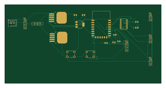
SEMG RECEIVER BOARD is an open source ESP8266 PCB design by Aaryaaaaaaa, published on GitHub. It is a 2-layer board measuring 142.8 × 72.3 mm, with 22 components from 12 distinct parts.
Its main chip is the ESP-12E, from the ESP8266 family. Other key parts include the LM2596S-5, AMS1117-3.3 and PCA9685BS. By type, the board carries 6 resistors, 5 ICs, 5 connectors, 3 switches, 2 capacitors and 1 battery holder.
It belongs with the iot & wireless, robotics & motion and power & battery designs in this gallery.
From the project
This is a 2-layer PCB for the receiver node of a wireless sEMG rehabilitation glove system, which receives gesture commands over ESP-NOW and drives three servos to move the glove's fingers accordingly.
Custom 2-layer PCB for the receiver node of a two-part wireless sEMG-based rehabilitation glove system. The transmitter node (worn on the unaffected arm) reads muscle signals via a Muscle BioAmp Patchy sensor, classifies the intended gesture, and sends it wirelessly (ESP-NOW) to this receiver, which drives three servos to move the affected-hand glove into the corresponding position (fist / open / pinch).
Main components on the SEMG RECEIVER BOARD
SEMG RECEIVER BOARD bill of materials (BOM)
22 components, 12 distinct parts.
| Qty | Part | Footprint | Refs |
|---|---|---|---|
| 2 | LM2596S-5 | TO-263-5_TabPin3 | U1, U2 |
| 1 | ESP-12E | ESP-12E | U3 |
| 1 | AMS1117-3.3 | SOT-223-3_TabPin2 | U4 |
| 1 | PCA9685BS | TSSOP-28_4.4x9.7mm_P0.65mm | U5 |
| 2 | Conn_01x04 | PinHeader_1x04_P2.54mm_Vertical | J1, J2 |
| 3 | Conn_01x03 | PinHeader_1x03_P2.54mm_Vertical | J3, J4, J5 |
| 1 | Battery | JST_XH_B2B-XH-AM_1x02_P2.50mm_Vertical | BT1 |
| 1 | SW_SPDT | SW_Slide-03_Wuerth-WS-SLTV_10x2.5x6.4_P2.54mm | SW1 |
| 2 | SW_Push | SW_PUSH_6mm | SW2, SW3 |
| 2 | 0.1uF | C_0805_2012Metric | C1, C2 |
| 4 | 10kΩ | R_0805_2012Metric | R1, R2, R3, R4 |
| 2 | 4.7kΩ | R_0805_2012Metric | R5, R6 |
SEMG RECEIVER BOARD design files
The KiCad project lives in the Aaryaaaaaaa/sEMG_RECEIVER_BOARD repository on GitHub; these links point at the commit this page was built from.
SEMG RECEIVER BOARD: common questions
What microcontroller does the SEMG RECEIVER BOARD use?
The SEMG RECEIVER BOARD is built around the ESP-12E, from the ESP8266 family.
How big is the SEMG RECEIVER BOARD?
The SEMG RECEIVER BOARD measures 142.8 × 72.3 mm, has 2 copper layers and is 1.6 mm thick.
How many components are on the SEMG RECEIVER BOARD?
22 components, from 12 distinct parts. The full bill of materials is listed on this page.
Where can I download the SEMG RECEIVER BOARD design files?
From the Aaryaaaaaaa/sEMG_RECEIVER_BOARD repository on GitHub, which has the KiCad layout and the schematic; the links under Design files point to each one.
Can I use the SEMG RECEIVER BOARD design in my own project?
The repository has no license, so all rights stay with Aaryaaaaaaa. Use it as a reference, and ask the author before reusing the design.
Can I test firmware for the SEMG RECEIVER BOARD without the hardware?
Yes. HardLabs builds a simulation of the board from its netlist and BOM, so you can run and debug ESP8266 firmware against it before you order a PCB.
Similar boards
 ESP8266
ESP8266ControllerCircuit
stuartpittaway
75 × 30 mm20 parts2LCC-BY-NC-4.01.1k ESP8266
HASwitchPlate
aderusha
60 × 40 mm8 parts2LMIT738 ESP8266
RatGDO-OpenSource-D1Mini-ESP8266
Kaldek
47.8 × 63.3 mm12 parts2LMIT506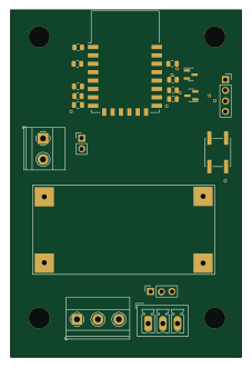 ESP8266
RatGDO-OpenSource-Bare-ESP8266
55 × 82.7 mm20 parts2LMIT506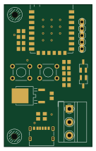 ESP8266
Goatgdo
32.9 × 53.3 mm23 parts2LMIT506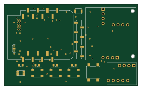 ESP8266
Iaq board
nkitanov
70.1 × 43.2 mm17 parts2LNo license398