
101 open source boards using the LM2596S-5
Real designs built with the LM2596S-5, from public GitHub projects: a quick way to see how others power, decouple and connect it. Each board comes with its KiCad files, full parts list and a render — and you can simulate its firmware on HardLabs.
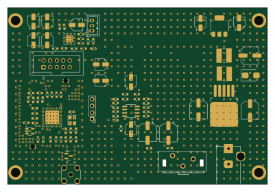
SI4684 SMD
PE5PVB
100 × 68 mm90 parts2LGPL-3.0131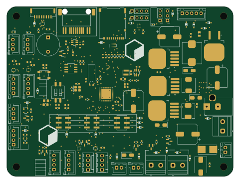 STM32
Mainboard
Cluradev
120 × 90 mm162 parts4LNo license118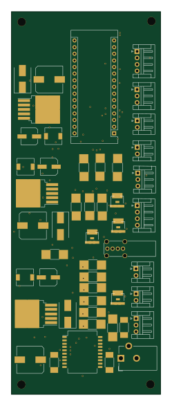 AVR/Arduino
Flypi
amchagas
57.2 × 146.6 mm49 parts2LGPL-2.087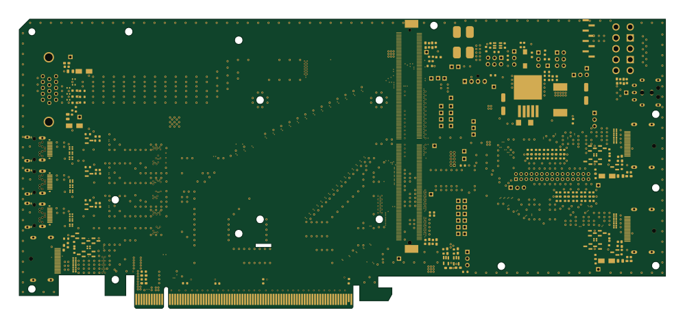
Mxm immobilizer
a-little-wifi
249.4 × 111.5 mm413 parts6LNo license74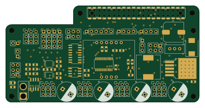 Raspberry Pi
Expansion board
reubenstr
100 × 49.8 mm75 parts4LMIT51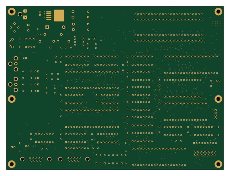
MSX ONE
jdgabbard
200 × 150 mm107 parts2LGPL-3.028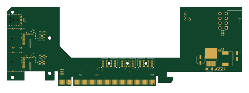
Dgff immobilizer
203.7 × 69 mm159 parts6LNo license11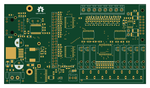 Raspberry Pi
OpenPLC
radioelf
129.5 × 72.6 mm163 parts2LNo license7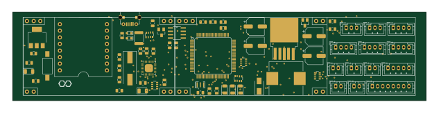 AVR/Arduino
TaggerMainboard
Infinitag
158 × 34 mm55 parts2LNo license6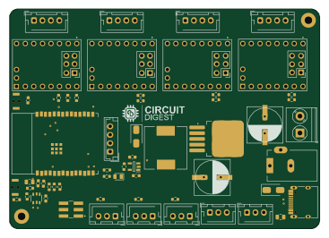 ESP32
SCARA-Robot-Based on-ESP32-C6
jobitjoseph
91.6 × 65 mm63 parts2LNo license4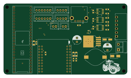 NXP
Teensy fendt-CAN
tomstix
112 × 64 mm46 parts2LNo license4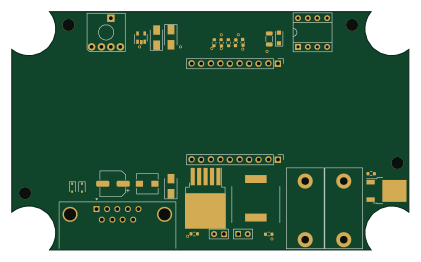 ESP32
Signalbroker lin transceiver
skyguru
105 × 63 mm29 parts2LApache-2.03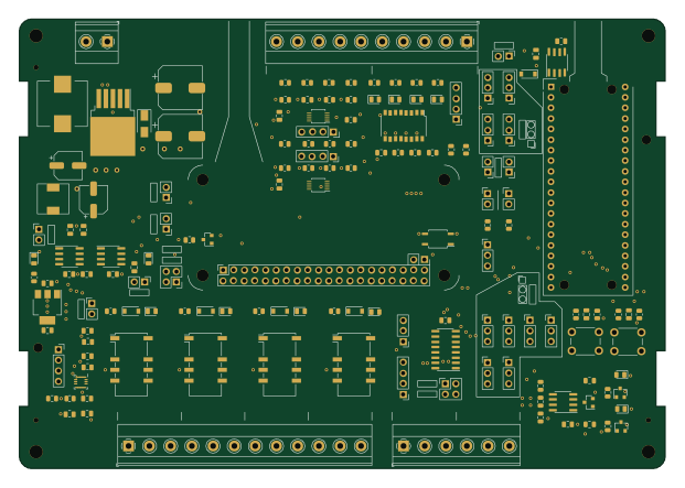 RP2040/RP2350
Nyu openplc te
kiwih
155 × 108 mm153 parts2LGPL-3.02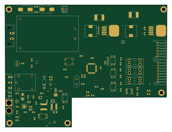 AVR/Arduino
1. PDU
SshgurkiratSingh
149.5 × 113 mm106 parts4LNo license2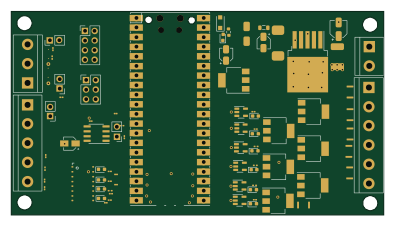 RP2040/RP2350
Piaa
soypat
98.6 × 53.8 mm104 parts2LGPL-2.02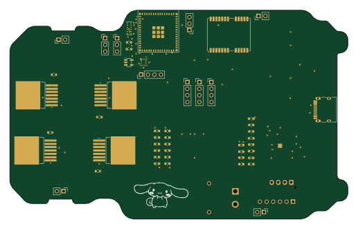 ESP32
Rc car
alaotach
129 × 79.8 mm85 parts4LNo license2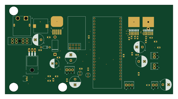 ESP32
RC Car Main Onboard
cjg-1
147.3 × 78.1 mm51 parts4LNo license2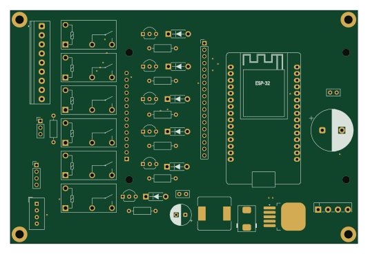 ESP32
ESP32-Simple-Thermostat
jrtaylor71
133 × 89.5 mm40 parts2LNo license2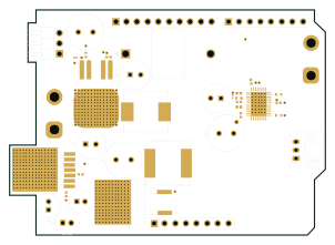
WROFutureEngineer
IaMaAVerYRANdOmPerSoN
75.4 × 53.8 mm38 parts2LGPL-3.02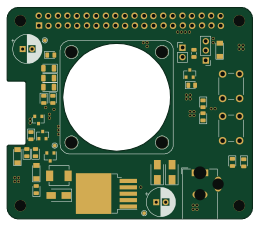
Pihat cooling
vanbwodonk
65 × 56 mm36 parts2LGPL-2.02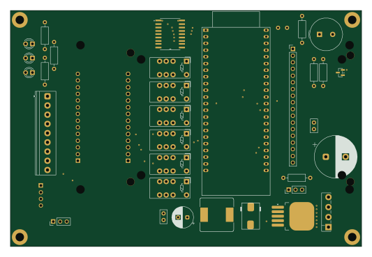 ESP32
ESP32-DevKitC3-Simple-Thermostat
133 × 89.5 mm32 parts4LNo license2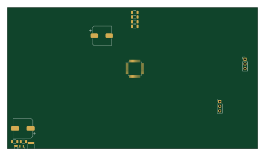 STM32
LED-Strip-Controller-Hardware
ScottGibb
134.6 × 76.2 mm167 parts2LGPL-3.01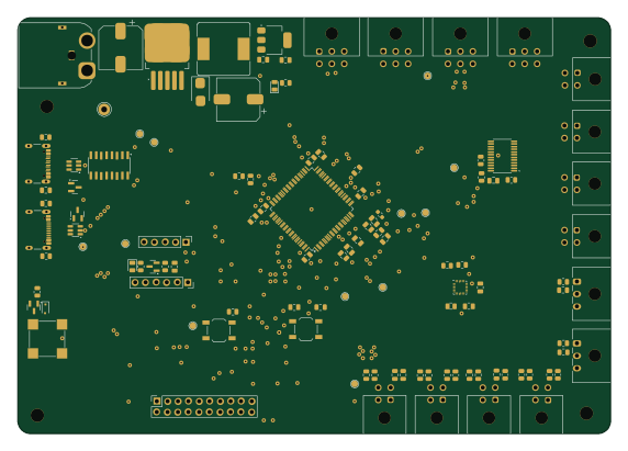 STM32
PCB AMR
ManuelOrtizCamacho
142.9 × 100.3 mm103 parts2LNo license1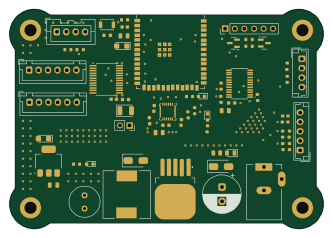 ESP32
RoboCore 2.0
AvishkaVishwa
83 × 58 mm64 parts2LNo license1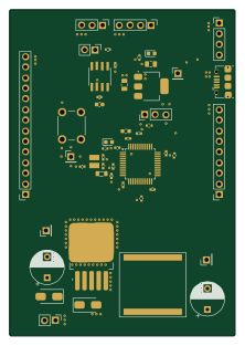 STM32
Stm32-can do dev board
kurtjd
54 × 78 mm49 parts2LMIT1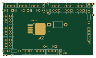
Rcs circuit diagram
explosion33
82 × 48 mm49 parts2LNo license1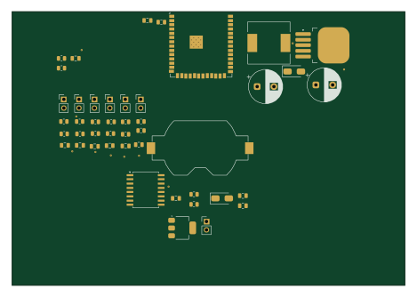 ESP32
PressLog
bansalsaksham
117 × 81.5 mm45 parts2LNo license1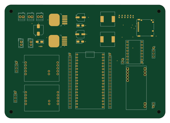 ESP32
MEOW System Integration
andrewgond
140.3 × 98.7 mm35 parts2LApache-2.01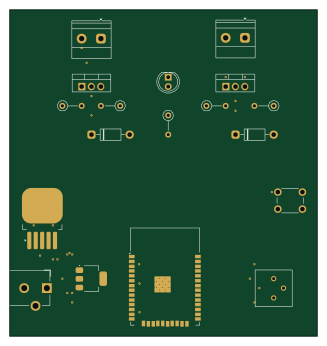 ESP32
Water-Dispenser
anadskman
81.3 × 86.4 mm18 parts2LNo license1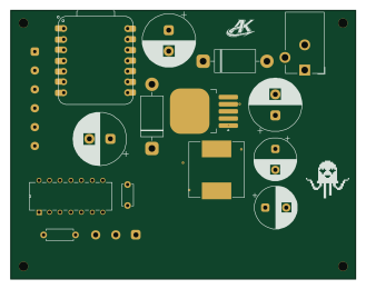 ESP32
AOILED
aoishik
82.1 × 64 mm16 parts2LNo license1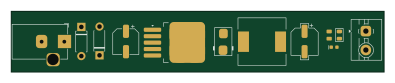
12V-to-5V-DC-Conveter
98.5 × 16 mm12 parts2LNo license1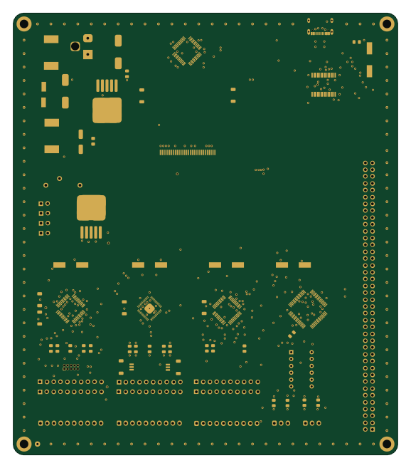 RP2040/RP2350
UniDebug
shreyask21
143 × 164 mm273 parts2LNo license0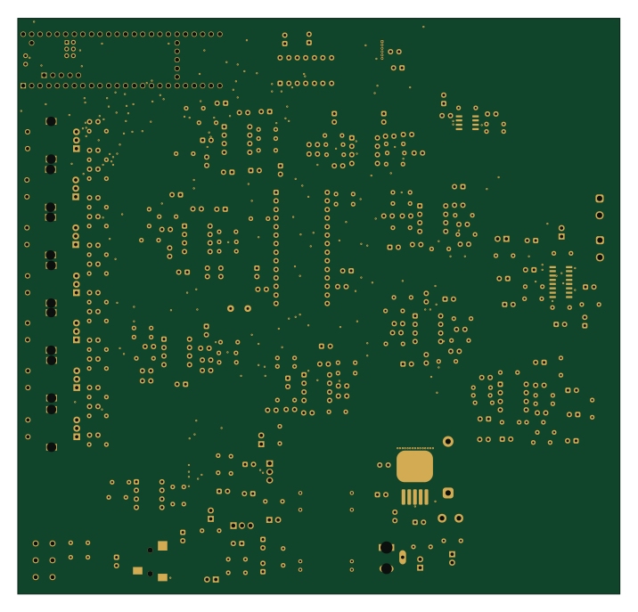 NXP
Spectrum-Audio-Amp
anasarif23
178.8 × 171 mm242 parts4LNo license0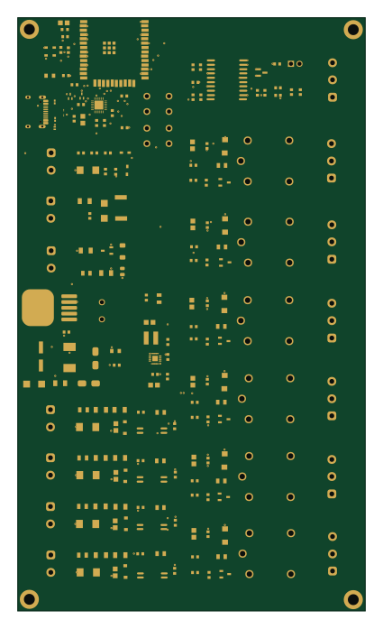 ESP32
Industrial IoT Controller
Hossam-Mamdouh
102 × 173.9 mm189 parts2LMIT0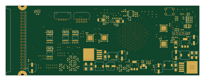 STM32
PUTM EV SMART FUSES 2022
PUT-Motorsport
166.4 × 60 mm169 parts4LNo license0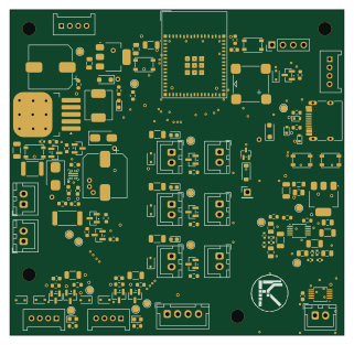 ESP32
Car iot services
karuru6225
80 × 78 mm131 parts2LNo license0
How designs wire the LM2596S-5
Read from the KiCad layouts of 88 open source designs, one per repository: what each pin of the LM2596S-5 connects to, and the resistors, capacitors and other passives placed on it.
- The OUT pin has a inductor on 79 of 88 designs, most often 33 µH (then 47 µH).
- The ON/OFF pin is tied to GND on 74 of 87 designs (12V on 3, a signal on 10).
- The FB pin is tied to 5V on 55 of 88 designs (not connected on 3, a signal on 29).
- The VIN pin has a decoupling capacitor on 37 of 88 designs, most often 100 nF (then 100 µF).
| Pin | Connected to | Parts on the pin |
|---|---|---|
| VINpin 1 | Connected to: 12V 68% · a signal 31% |
|
| OUTpin 2 | Connected to: Signal 95% |
|
| GNDpin 3 | Connected to: GND 94% | — |
| FBpin 4 | Connected to: 5V 63% · a signal 33% | — |
| ON/OFFpin 5 | Connected to: GND 85% | — |
Connections count pins, parts count designs; values in brackets are how many parts had that value. Designs read include SI4684 SMD by PE5PVB, Mainboard by Cluradev, Flypi by amchagas and Mxm immobilizer by a-little-wifi.
The LM2596S-5 in open source designs
The gallery holds 101 open source boards using the LM2596S-5 from 91 GitHub repositories; a typical one measures about 98.5 × 76.1 mm and carries around 49 components.
79% are two-layer designs, the rest use four layers or more, and 28% carry an open source license.
The most starred is SI4684 SMD by PE5PVB.
Parts used alongside the LM2596S-5
Microcontrollers on boards using the LM2596S-5
What boards using the LM2596S-5 are built for
LM2596S-5: common questions
Where can I find a LM2596S-5 reference design?
Each of the 101 boards on this page is a real design using the LM2596S-5. Open one to see how it is wired up, with the full BOM, a render of the layout and links to its KiCad files.
How is the LM2596S-5 OUT pin connected?
The OUT pin has a inductor on 79 of 88 designs, most often 33 µH (then 47 µH). Counted from the KiCad layouts of 88 open source designs using the LM2596S-5.
How is the LM2596S-5 ON/OFF pin connected?
The ON/OFF pin is tied to GND on 74 of 87 designs (12V on 3, a signal on 10). Counted from the KiCad layouts of 88 open source designs using the LM2596S-5.
How is the LM2596S-5 FB pin connected?
The FB pin is tied to 5V on 55 of 88 designs (not connected on 3, a signal on 29). Counted from the KiCad layouts of 88 open source designs using the LM2596S-5.
What parts are used alongside the LM2596S-5?
The AMS1117-3.3, TB6612FNG, LM2596S-3.3, ADS1115IDGS and ESP32-S3-WROOM-1 appear in the most repositories here.
Which microcontrollers do boards using the LM2596S-5 use?
Most are built on ESP32 (35), STM32 (15), AVR/Arduino (9) and ESP8266 (5).
How big is a typical board using the LM2596S-5?
The median is 98.5 × 76.1 mm, and 79% are two-layer designs.
What is the most popular open source board using the LM2596S-5?
By GitHub stars, SI4684 SMD by PE5PVB, with 131 stars.
Can I simulate one of these boards using the LM2596S-5 before building it?
Yes. HardLabs turns a board's netlist and BOM into a working simulation, so you can boot and test firmware against it with no hardware on your desk.