
A0 IoT GATEWAY

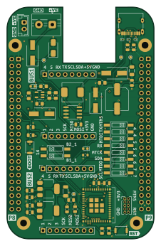
About the A0 IoT GATEWAY PCB
A0 IoT GATEWAY is an open source ESP32 PCB design by absmach, published on GitHub under the Apache-2.0 license. It is a 4-layer board measuring 54.6 × 86.3 mm, with 57 components from 34 distinct parts.
Its main chip is the ESP32-C6-MINI-1/U, from the ESP32 family. Other key parts include the SMXS-02K-TP, MCP73831-2-OT, XL1509-5.0 and AMS1117-3.3. By type, the board carries 14 capacitors, 11 resistors, 10 connectors, 10 diodes, 6 ICs and 3 switches.
It belongs with the iot & wireless, rf & radio and power & battery designs in this gallery.
From the project
A0 IoT Gateway
A0 is the base board of the modular A0 IoT gateway, built around an ESP32-C6 module (RISC-V, Wi-Fi 6, Bluetooth 5, IEEE 802.15.4).
The ESP32-C6 is Espressif's first Wi-Fi 6 SoC, integrating 2.4 GHz Wi-Fi 6 (802.11ax), Bluetooth 5 (LE) and IEEE 802.15.4 (Thread/Zigbee) radio connectivity in a single low-power chip (product page).
Wi-Fi 6 features (OFDMA, MU-MIMO, TWT) deliver low latency and long battery life even in congested RF environments, while combined Wi-Fi + BLE + 802.15.4 support makes it a natural fit for Matter end-point devices, Thread Border Routers, and Zigbee bridges.
Main components on the A0 IoT GATEWAY
A0 IoT GATEWAY bill of materials (BOM)
57 components, 34 distinct parts — part numbers from the project's BOM.
| Qty | Part | Footprint | Refs |
|---|---|---|---|
| 1 | SMXS-02K-TP SM Switch | C5439761 | U1 |
| 1 | ESP32-C6-MINI-1/U | XCVR_ESP32-C3-MINI-1U-N4 | U4 |
| 1 | MCP73831-2-OT | SOT-23-5 | U5 |
| 1 | XL1509-5.0 | SOIC-8_3.9x4.9mm_P1.27mm | U6 |
| 2 | AMS1117-3.3 | SOT-223-3_TabPin2 | U7, U8 |
| 4 | CONN_01X08 Conn_01x08 | PinSocket_1x08_P2.54mm_Vertical | J1, J2, J3, J4 |
| 1 | C725895 Beagle P8 | PinHeader_2x23_P2.54mm_Vertical | J5 |
| 1 | C725895 Beagle P9 | PinHeader_2x23_P2.54mm_Vertical | J6 |
| 1 | C2765186 ESP32 USB | USB_C_Receptacle_G-Switch_GT-USB-7010ASV | J7 |
| 1 | SCREW_TERMINAL_01X02 Screw_Terminal_01x02 | TerminalBlock_MaiXu_MX126-5.0-02P_1x02_P5.00mm | J8 |
| 1 | BAT_JST_01X02 BAT_JST_01x02 | JST_EH_B2B-EH-A_1x02_P2.50mm_Vertical | J9 |
| 1 | CONN_ARM_JTAG_SWD_10 Conn_ARM_JTAG_SWD_10 | PinHeader_2x05_P1.27mm_Vertical | J10 |
| 1 | C3105 Fuse | Fuse_1206_3216Metric | F1 |
| 2 | SW_Push | SW_Push_SPST_NO_Alps_SKRK | SW1, SW2 |
| 1 | SMXS-08K-TP SM Switch | C5439767 | SW5 |
| 4 | C8678 40V 3A 550mV@3A Schottky | D_SMA-SMB_Universal_Handsoldering | D1, D7, D8, D9 |
| 3 | ESD9B5.0ST5G | D_SOD-923 | D2, D3, D4 |
| 1 | BZV55C27 | D_SMA | D5 |
| 2 | LED | LED_0603_1608Metric | D6, D10 |
| 1 | C668306 FerriteBead | L_1206_3216Metric_Pad1.22x1.90mm_HandSolder | FB1 |
Show 14 more
| Qty | Part | Footprint | Refs |
|---|---|---|---|
| 1 | 47UH/2A 47uH/2A | L_Chilisin_BMRB00060624 | L1 |
| 2 | 1UF 1uF | C_0805_2012Metric | C1, C2 |
| 1 | 22UF 22uF | C_0805_2012Metric | C3 |
| 3 | 0.1UF 0.1uF | C_0805_2012Metric | C4, C10, C11 |
| 3 | 4.7UF 4.7uF | C_0805_2012Metric_Pad1.18x1.45mm_HandSolder | C5, C6, C7 |
| 4 | 10UF 10uF | C_0805_2012Metric | C8, C9, C12, C13 |
| 1 | 330UF 330uF | C_Elec_8x10.2 | C14 |
| 3 | 10K | R_0805_2012Metric | R1, R4, R5 |
| 2 | 2.2K | R_0805_2012Metric | R2, R3 |
| 2 | 5K1 | R_0805_2012Metric | R6, R7 |
| 1 | 2k | R_0805_2012Metric_Pad1.20x1.40mm_HandSolder | R8 |
| 1 | 220 | R_0805_2012Metric_Pad1.20x1.40mm_HandSolder | R9 |
| 1 | 10K 10k | R_0805_2012Metric_Pad1.20x1.40mm_HandSolder | R10 |
| 1 | 220 | R_0603_1608Metric | R11 |
A0 IoT GATEWAY design files
The KiCad project lives in the absmach/a0 repository on GitHub; these links point at the commit this page was built from.
- Layouta0/a0.kicad_pcb
- Schematica0/a0.kicad_sch
- BOMa0/jlcpcb/production_files/BOM-a0.csv
A0 IoT GATEWAY: common questions
What microcontroller does the A0 IoT GATEWAY use?
The A0 IoT GATEWAY is built around the ESP32-C6-MINI-1/U, from the ESP32 family.
How big is the A0 IoT GATEWAY PCB?
The A0 IoT GATEWAY measures 54.6 × 86.3 mm, has 4 copper layers and is 1.6 mm thick.
How many components are on the A0 IoT GATEWAY?
57 components, from 34 distinct parts, with part numbers taken from the project's own BOM. The full bill of materials is listed on this page.
Where can I download the A0 IoT GATEWAY design files?
From the absmach/a0 repository on GitHub, which has the KiCad layout, the schematic and the BOM; the links under Design files point to each one.
Can I use the A0 IoT GATEWAY design in my own project?
Yes, under the terms of its Apache-2.0 license, which absmach chose for the repository.
Can I test firmware for the A0 IoT GATEWAY without the hardware?
Yes. HardLabs builds a simulation of the board from its netlist and BOM, so you can run and debug ESP32 firmware against it before you order a PCB.
More boards in a0
Similar boards
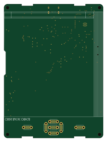 ESP32
Open Book Abridged Edition
joeycastillo
85 × 115 mm65 parts2LCC-BY-SA-4.08.1k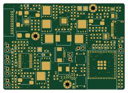 ESP32
Powertrain
byrantech
64 × 45.4 mm171 parts4LMIT4.3k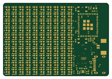 ESP32
Badge
atopile
56.3 × 39 mm239 parts4LMIT4.0k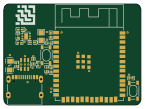 ESP32
Esp32 minimal
36.2 × 26.8 mm20 parts2LMIT4.0k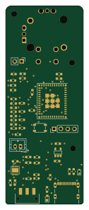 ESP32
Controller
StuckAtPrototype
29 × 74 mm58 parts4LApache-2.03.8k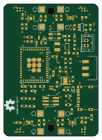 ESP32
Racer
36 × 50.2 mm70 parts4LApache-2.03.8k