
Hyperactive radio

About the Hyperactive radio PCB
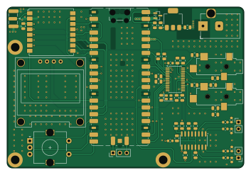
Hyperactive radio is an open source RP2040/RP2350 PCB design by activexray, published on GitHub. It is a 4-layer board measuring 88 × 60 mm, with 52 components from 23 distinct parts.
Its main chip is the RaspberryPi_Pico, from the RP2040/RP2350 family. Other key parts include the LD1117S50TR_SOT223, Ai-Thinker-Ra-01, PCM3060PWR, SSD1306 and PAM8406DR. By type, the board carries 25 capacitors, 7 connectors, 6 inductors, 5 ICs, 5 resistors and 1 module.
It belongs with the rf & radio and audio designs in this gallery.
From the project
Firmware for experimental ISM-band audio transmission
Experimental real-time, long-range, high-quality, wireless digital audio for Hyperactive 2026.
64 kbps stereo Opus at 48 kHz should be transparent for most program material — comparable to a good 128 kbps MP3, but with lower latency and better behaviour at the edges of the bitrate. The fixed-point build removes float entirely; no performance penalty on Cortex-M33 which has a hardware FPU but where the float Opus path was benchmarked to be slower than fixed-point.
Main components on the Hyperactive radio
Hyperactive radio bill of materials (BOM)
52 components, 23 distinct parts.
| Qty | Part | Footprint | Refs |
|---|---|---|---|
| 1 | LD1117S50TR_SOT223 | SOT-223-3_TabPin2 | U1 |
| 1 | Ai-Thinker-Ra-01 | Ai-Thinker-Ra-01-LoRa | U2 |
| 1 | PCM3060PWR PCM3060 | TSSOP-28_4.4x9.7mm_P0.65mm | U3 |
| 1 | SSD1306 | SSD1306_0.96_Oled | U4 |
| 1 | PAM8406DR PAM8406D | SOIC-16_3.9x9.9mm_P1.27mm | U6 |
| 1 | RaspberryPi_Pico | RaspberryPi_Pico_SMD_HandSolder | A1 |
| 1 | DMG2305UX | SOT-23 | Q1 |
| 1 | X1G0041710019 SG-210STF | Oscillator_SMD_SeikoEpson_SG210-4Pin_2.5x2.0mm | Y1 |
| 1 | Barrel_Jack_MountingPin | BarrelJack_Horizontal | J1 |
| 1 | Conn_01x03_Pin | PinHeader_1x03_P2.54mm_Vertical | J2 |
| 2 | Conn_01x02 | PinHeader_1x02_P2.54mm_Vertical | J3, J7 |
| 1 | Conn_Coaxial | SMA_Samtec_SMA-J-P-H-ST-EM1_EdgeMount | J4 |
| 2 | SJ-3524-SMT-TR AudioJack3_SwitchT | Jack_3.5mm_CUI_SJ-3524-SMT_Horizontal | J8, J9 |
| 1 | EC11E18244A5 RotaryEncoder_Switch_MP | RotaryEncoder_Alps_EC11E-Switch_Vertical_H20mm | SW1 |
| 6 | BLM18PG221SN1 | L_0603_1608Metric | FB1, FB6, FB7, FB8, FB9, FB10 |
| 10 | CL21A106KOQNNNG 10u | C_0805_2012Metric | C1, C3, C6, C8, C10, C12, C13, C14 +2 |
| 1 | GRM21BR61A226ME51L 22u | C_0805_2012Metric | C2 |
| 7 | 0805ZD104KAT2A 100n | C_0805_2012Metric | C4, C7, C9, C11, C18, C19, C20 |
| 3 | 0805X105K160CT 1u | C_0805_2012Metric | C21, C22, C27 |
| 4 | C0603C221J1HACAUTO 220p | C_0603_1608Metric | C23, C24, C25, C26 |
Show 3 more
| Qty | Part | Footprint | Refs |
|---|---|---|---|
| 1 | RG2012P-104-B-T5 100k | R_0805_2012Metric | R1 |
| 3 | RG2012P-472-D-T5 4.7k | R_0805_2012Metric | R2, R3, R4 |
| 1 | RG2012P-223-B-T5 22k | R_0805_2012Metric | R7 |
Hyperactive radio design files
The KiCad project lives in the activexray/hyperactive_radio repository on GitHub; these links point at the commit this page was built from.
Hyperactive radio: common questions
What microcontroller does the Hyperactive radio use?
The Hyperactive radio is built around the RaspberryPi_Pico, from the RP2040/RP2350 family.
How big is the Hyperactive radio PCB?
The Hyperactive radio measures 88 × 60 mm, has 4 copper layers and is 1.6 mm thick.
How many components are on the Hyperactive radio?
52 components, from 23 distinct parts. The full bill of materials is listed on this page.
Where can I download the Hyperactive radio design files?
From the activexray/hyperactive_radio repository on GitHub, which has the KiCad layout and the schematic; the links under Design files point to each one.
Can I use the Hyperactive radio design in my own project?
The repository has no license, so all rights stay with activexray. Use it as a reference, and ask the author before reusing the design.
Can I test firmware for the Hyperactive radio without the hardware?
Yes. HardLabs builds a simulation of the board from its netlist and BOM, so you can run and debug RP2040/RP2350 firmware against it before you order a PCB.
Similar boards
 RP2040/RP2350
Open Book Abridged Edition
joeycastillo
85 × 115 mm29 parts2LCC-BY-SA-4.08.1k RP2040/RP2350
Corne
foostan
277.2 × 107.5 mm164 parts2LCC-BY-4.07.7k RP2040/RP2350
Corne
277.2 × 107.5 mm164 parts2LCC-BY-4.07.7k RP2040/RP2350
LogicAnalyzer
gusmanb
57 × 55.2 mm6 parts2LGPL-3.05.0k RP2040/RP2350
Jitx design
55.5 × 65 mm26 parts4LGPL-3.05.0k RP2040/RP2350
Pro V2
kata0510
290.1 × 130 mm270 parts2LMIT2.3k