
Laser controller

About the Laser controller PCB
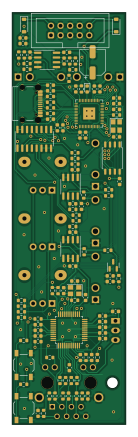
Laser controller is an open source RP2040/RP2350 PCB design by adeboni, published on GitHub under the GPL-3.0 license. It is a 2-layer board measuring 30 × 109 mm, with 124 components from 43 distinct parts.
Its main chip is the RP2040, from the RP2040/RP2350 family. Other key parts include the MCP3208, MCP6002-XSN, W5500, W25Q128JVS and LM4040B50FTA. By type, the board carries 49 resistors, 47 capacitors, 9 ICs, 8 connectors, 3 diodes and 2 crystals.
It belongs with the audio designs in this gallery.
From the project
This repository stores various eurorack module designs I've made
This repository stores various eurorack module designs I've made.
BT Module: Allows you to pair your phone or computer and outputs stereo audio Dodecamodulator: 12 individually configurable LFOs through an onboard UI or through Bluetooth Geiger Clock Module: Uses a Geiger–Müller tube to generate pulses Google Assistant Module: A Google Home Mini in a eurorack form-factor Neopixel Controller Module: Can control neopixel rainbow cycle speed, brightness, and VU-meter-style amplitude with CV CS:GO Game State Integration Server: Receives events from CS:GO and enables gate outputs based on game…
Main components on the Laser controller
Laser controller bill of materials (BOM)
124 components, 43 distinct parts — part numbers from the project's BOM.
| Qty | Part | Footprint | Refs |
|---|---|---|---|
| 1 | MCP3208 | SOIC-16_3.9x9.9mm_P1.27mm | U1 |
| 3 | MCP6002-XSN MCP6002-xSN | SOIC-8_3.9x4.9mm_P1.27mm | U2, U3, U8 |
| 1 | RP2040 | QFN-56-1EP_7x7mm_P0.4mm_EP3.2x3.2mm | U4 |
| 1 | W5500 | LQFP-48_7x7mm_P0.5mm | U5 |
| 1 | W25Q128JVS | SOIC-8_5.23x5.23mm_P1.27mm | U7 |
| 1 | LM4040B50FTA LM4040-5V Diodes Incorporated | SOT-23 | U9 |
| 1 | R-783.3-1.0 | Converter_DCDC_RECOM_R-78E-0.5_THT | U10 |
| 1 | 12MHZ 12MHz | Crystal_SMD_3225-4Pin_3.2x2.5mm | Y1 |
| 1 | 25MHZ 25MHz | Crystal_SMD_3225-4Pin_3.2x2.5mm | Y2 |
| 5 | AudioJack2_SwitchT | Jack_3.5mm_QingPu_WQP-PJ398SM_Vertical_CircularHoles | J1, J2, J3, J4, J5 |
| 1 | Conn_02x05_Odd_Even | IDC-Header_2x05_P2.54mm_Vertical | J6 |
| 1 | USB_C_RECEPTACLE_USB2.0 USB_C_Receptacle_USB2.0 | USB_C_Receptacle_Palconn_UTC16-G | J14 |
| 1 | SI-46001-F | BEL_SI-46001-F | J16 |
| 3 | 1M | Potentiometer_Alpha_RD901F-40-00D_Single_Vertical | RV1, RV2, RV3 |
| 2 | SW_Push | SW_SPST_TL3342 | SW2, SW3 |
| 1 | LED | LED_0603_1608Metric | D1 |
| 2 | SM4007 | D_SOD-123 | D3, D5 |
| 1 | C1002 FerriteBead | L_0603_1608Metric | FB1 |
| 25 | 100N 100n | C_0603_1608Metric | C1, C2, C3, C4, C5, C6, C7, C8 +17 |
| 4 | 1u | C_0603_1608Metric | C10, C11, C47, C48 |
Show 23 more
| Qty | Part | Footprint | Refs |
|---|---|---|---|
| 2 | 27P 27p | C_0603_1608Metric | C22, C25 |
| 2 | 18P 18p | C_0603_1608Metric | C23, C26 |
| 1 | 4.7U 4.7u | C_0603_1608Metric | C27 |
| 1 | 22N 22n | C_0603_1608Metric | C28 |
| 2 | 6.8N 6.8n | C_0603_1608Metric | C30, C31 |
| 4 | 10U 10u | C_0603_1608Metric | C34, C35, C44, C45 |
| 5 | 470P 470p | C_0603_1608Metric | C38, C39, C40, C41, C42 |
| 1 | 100U 100u | CP_Elec_6.3x5.4 | C49 |
| 10 | 100K 100k | R_0603_1608Metric | R1, R4, R6, R7, R10, R11, R14, R15 +2 |
| 5 | 75K 75k | R_0603_1608Metric | R2, R5, R9, R13, R17 |
| 5 | 27K 27k | R_0603_1608Metric | R3, R8, R12, R16, R20 |
| 1 | 2k | R_0603_1608Metric | R21 |
| 5 | 4.7K 4.7k | R_0603_1608Metric | R22, R24, R52, R57, R59 |
| 2 | 3.3K 3.3k | R_0603_1608Metric | R23, R25 |
| 2 | 27 | R_0603_1608Metric | R45, R46 |
| 2 | 5.1K 5.1k | R_0603_1608Metric | R51, R54 |
| 4 | 4.7 | R_0603_1608Metric | R53, R55, R56, R58 |
| 4 | 49.9 | R_0603_1608Metric | R60, R61, R62, R63 |
| 1 | 1M | R_0603_1608Metric | R68 |
| 4 | 1k | R_0603_1608Metric | R69, R73, R77, R78 |
| 2 | 470 | R_0603_1608Metric | R70, R71 |
| 1 | 10 | R_0603_1608Metric | R72 |
| 1 | 12.4K 12.4k | R_0603_1608Metric | R74 |
Laser controller design files
The KiCad project lives in the adeboni/eurorack repository on GitHub; these links point at the commit this page was built from.
Laser controller: common questions
What microcontroller does the Laser controller use?
The Laser controller is built around the RP2040, from the RP2040/RP2350 family.
How big is the Laser controller PCB?
The Laser controller measures 30 × 109 mm, has 2 copper layers and is 1.6 mm thick.
How many components are on the Laser controller?
124 components, from 43 distinct parts, with part numbers taken from the project's own BOM. The full bill of materials is listed on this page.
Where can I download the Laser controller design files?
From the adeboni/eurorack repository on GitHub, which has the KiCad layout, the schematic and the BOM; the links under Design files point to each one.
Can I use the Laser controller design in my own project?
Yes, under the terms of its GPL-3.0 license, which adeboni chose for the repository.
Can I test firmware for the Laser controller without the hardware?
Yes. HardLabs builds a simulation of the board from its netlist and BOM, so you can run and debug RP2040/RP2350 firmware against it before you order a PCB.
More boards in eurorack
Noise toaster
128 × 129 mm133 parts2LGPL-3.01
Mega 12v pwr
185 × 144 mm67 parts2LGPL-3.01
Bt module
10 × 108 mm46 parts2LGPL-3.01
Ecg
10 × 100 mm41 parts2LGPL-3.01
Power bus
420 × 40 mm34 parts2LGPL-3.01
Keystep expander module
40.3 × 100 mm24 parts2LGPL-3.01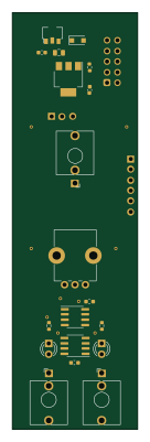 RP2040/RP2350
Ecg carrier
30 × 100 mm22 parts2LGPL-3.01
Line out
9.8 × 104 mm16 parts2LGPL-3.01
Mini 12v pwr
26.4 × 23.3 mm8 parts2LGPL-3.01
Dc isolator
33.2 × 24.5 mm8 parts2LGPL-3.01
12v power
77 × 37 mm7 parts2LGPL-3.01
Similar boards
 RP2040/RP2350
Open Book Abridged Edition
joeycastillo
85 × 115 mm29 parts2LCC-BY-SA-4.08.1k RP2040/RP2350
Corne
foostan
277.2 × 107.5 mm164 parts2LCC-BY-4.07.7k RP2040/RP2350
Corne
277.2 × 107.5 mm164 parts2LCC-BY-4.07.7k RP2040/RP2350
LogicAnalyzer
gusmanb
57 × 55.2 mm6 parts2LGPL-3.05.0k RP2040/RP2350
Jitx design
55.5 × 65 mm26 parts4LGPL-3.05.0k RP2040/RP2350
Pro V2
kata0510
290.1 × 130 mm270 parts2LMIT2.3k