
PROJ500 - Auxillary IMU Board

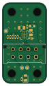
About the PROJ500 - Auxillary IMU Board
PROJ500 - Auxillary IMU Board is an open source PCB design by AislingBee, published on GitHub. It is a 2-layer board measuring 17.2 × 31.4 mm, with 14 components from 10 distinct parts.
Other key parts include the LSM6DSOX. By type, the board carries 6 resistors, 4 capacitors, 1 IC, 1 connector, 1 diode and 1 inductor.
It belongs with the sensors designs in this gallery.
From the project
The Github Repository for MEng project 2025/26
Author: Charlie Date: May 2026 Project: MEng PROJ500 — Plymouth Humanoid Robot
This folder contains all hardware and firmware deliverables produced during the 2025–26 academic year. It is structured into three top-level areas:
The robot's electronic architecture is split across two custom boards:
The PDU and RCU communicate over a dedicated management CAN bus (250 kbps). The RCU talks to the Thor AI computer (Jetson/PC) over UDP/Ethernet. Motors are driven by the RCU over two 1 Mbps CAN buses using the RobStride RS04 private protocol.
Main components on the PROJ500 - Auxillary IMU Board
PROJ500 - Auxillary IMU Board bill of materials (BOM)
14 components, 10 distinct parts — part numbers from the project's BOM.
| Qty | Part | Footprint | Refs |
|---|---|---|---|
| 1 | LSM6DSOX | ST_LGA-14L_2.5x3.0mm_P0.5mm_4x3 | U1 |
| 1 | RCU | Molex_Micro-Fit_3.0_43045-0812_2x04_P3.00mm_Vertical | J1 |
| 1 | GR_PWR | D_0805_2012Metric | D1 |
| 1 | 120R/3A | L_0603_1608Metric | FB1 |
| 2 | 100nF/50V(10%) | C_0402_1005Metric | C1, C2 |
| 2 | 4.7uF/16V(10%) | C_0805_2012Metric | C3, C4 |
| 3 | 0R(10%) | R_0402_1005Metric | R1, R3, R4 |
| 1 | 100k(10%) | R_0402_1005Metric | R2 |
| 1 | 22R(1%) | R_0402_1005Metric | R5 |
| 1 | 1k(10%) | R_0402_1005Metric | R6 |
PROJ500 - Auxillary IMU Board design files
The KiCad project lives in the AislingBee/MEng-PROJ500-2025-26 repository on GitHub; these links point at the commit this page was built from.
PROJ500 - Auxillary IMU Board: common questions
How big is the PROJ500 - Auxillary IMU Board?
The PROJ500 - Auxillary IMU Board measures 17.2 × 31.4 mm, has 2 copper layers and is 1.6 mm thick.
How many components are on the PROJ500 - Auxillary IMU Board?
14 components, from 10 distinct parts, with part numbers taken from the project's own BOM. The full bill of materials is listed on this page.
Where can I download the PROJ500 - Auxillary IMU Board design files?
From the AislingBee/MEng-PROJ500-2025-26 repository on GitHub, which has the KiCad layout, the schematic and the BOM; the links under Design files point to each one.
Can I use the PROJ500 - Auxillary IMU Board design in my own project?
The repository has no license, so all rights stay with AislingBee. Use it as a reference, and ask the author before reusing the design.
More boards in MEng-PROJ500-2025-26
 STM32
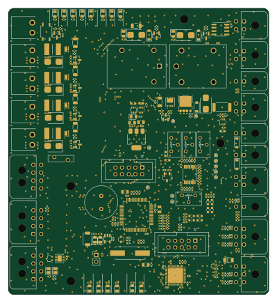
STM32PROJ500 - Power Distribution Board
99.1 × 108.6 mm297 parts2LNo license0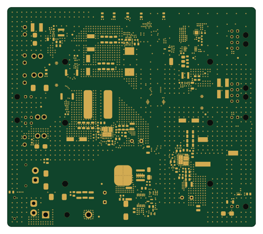
PROJ500 - Power Supply Board
130 × 115 mm256 parts2LNo license0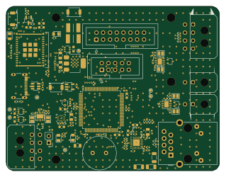 ESP32
ESP32PROJ500 - Real-Time Control Unit
79.6 × 61.4 mm137 parts2LNo license0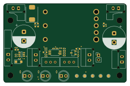
PROJ500 - Braking Chopper Controller
67.2 × 43.3 mm48 parts2LNo license0
Similar boards

Sensor smd
scottbez1
40 × 20 mm5 parts2LApache-2.04.2k
Sensors
StuckAtPrototype
15.2 × 9 mm14 parts4LApache-2.03.8k
Microphone
Mentra-Community
5.5 × 6.1 mm6 parts2LMIT1.2k
TemperaturePCB PANEL
stuartpittaway
116 × 75.5 mm178 parts2LCC-BY-NC-4.01.1k
Pots
shanteacontrols
390 × 93 mm75 parts2LApache-2.0956
ButtonsLEDs
390 × 37 mm82 parts2LApache-2.0956