
Boost converter

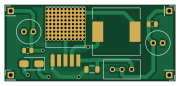
About the Boost converter PCB
Boost converter is an open source PCB design by ajkumar-1907, published on GitHub under the MIT license. It is a 2-layer board measuring 45 × 20 mm, with 13 components from 9 distinct parts.
By type, the board carries 4 connectors, 4 capacitors, 1 diode, 1 inductor and 1 resistor.
It belongs with the power & battery designs in this gallery.
From the project
Open-source library of power electronics converter topologies — KiCad schematics, working principles, use cases, and design notes for DC-DC, AC-DC, DC-AC, and AC-AC converters. Free to use, modify, and build on.
An adjustable step-up DC-DC converter built around the XL6009 switching regulator. It raises a lower DC input to a higher, regulated DC output, which you set with a multi-turn trimmer.
The boost converter is the basic step-up switch-mode topology. Energy is stored in an inductor while a switch is on, then released to the output, on top of the input voltage, while the switch is off. The XL6009 integrates the power switch (4 A), oscillator (400 kHz) and control loop, so the design needs only an inductor, a Schottky diode, capacitors and a feedback divider.
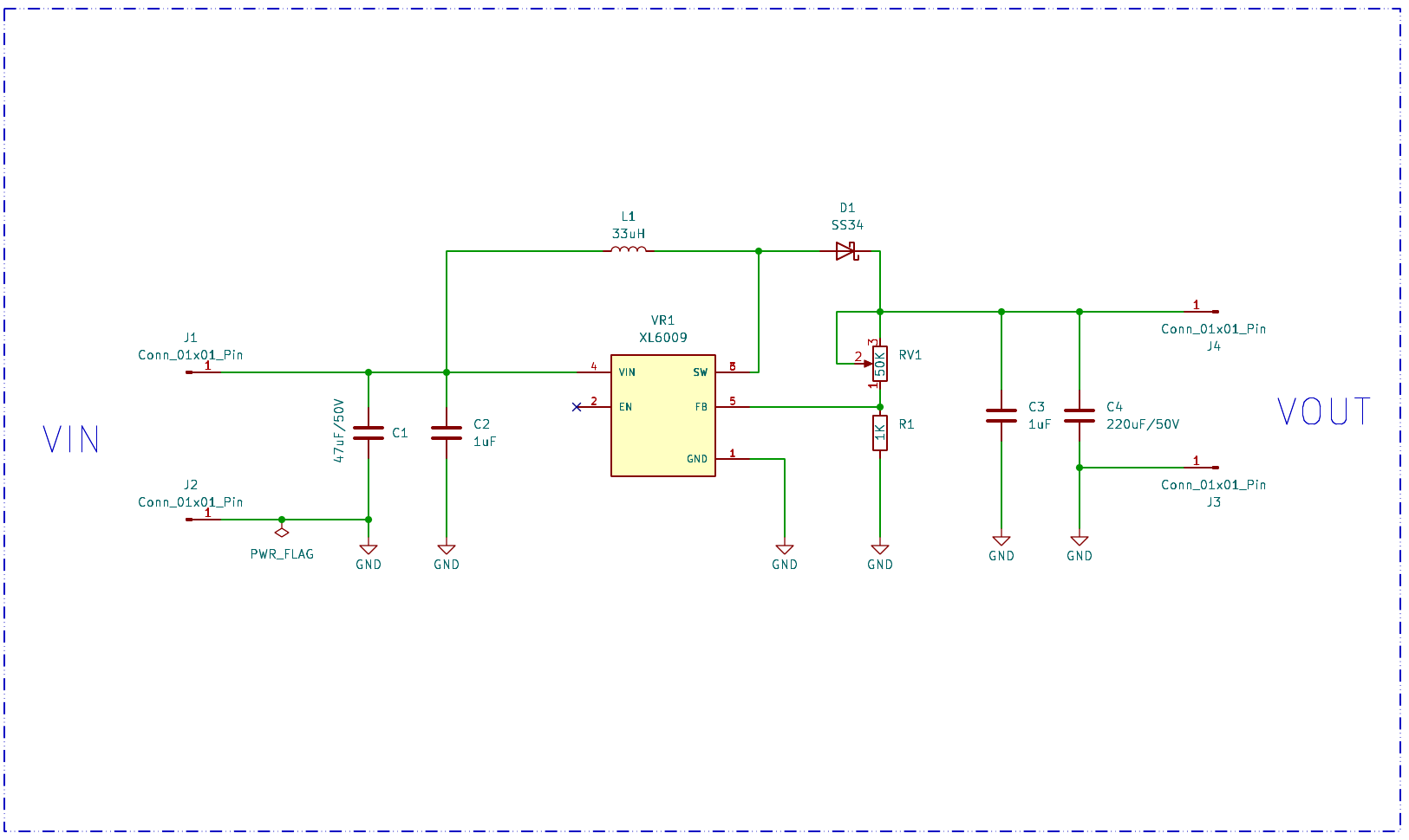
Boost converter bill of materials (BOM)
13 components, 9 distinct parts.
| Qty | Part | Footprint | Refs |
|---|---|---|---|
| 4 | Conn_01x01_Pin | PinHeader_1x01_P2.54mm_Vertical | J1, J2, J3, J4 |
| 1 | 50K | Potentiometer_Bourns_3296W_Vertical | RV1 |
| 1 | XL6009 | XL6009 | VR1 |
| 1 | SS34 | D_SMA | D1 |
| 1 | 33uH | L_12x12mm_H8mm | L1 |
| 1 | 47uF/50V | C_Radial_D6.3mm_H11.0mm_P2.50mm | C1 |
| 2 | 1uF | C_0805_2012Metric | C2, C3 |
| 1 | 220uF/50V | C_Radial_D6.3mm_H11.0mm_P2.50mm | C4 |
| 1 | 1K | R_1206_3216Metric | R1 |
Boost converter design files
The KiCad project lives in the ajkumar-1907/power-converter-lib repository on GitHub; these links point at the commit this page was built from.
Boost converter: common questions
How big is the Boost converter PCB?
The Boost converter measures 45 × 20 mm, has 2 copper layers and is 1.6 mm thick.
How many components are on the Boost converter?
13 components, from 9 distinct parts. The full bill of materials is listed on this page.
Where can I download the Boost converter design files?
From the ajkumar-1907/power-converter-lib repository on GitHub, which has the KiCad layout and the schematic; the links under Design files point to each one.
Can I use the Boost converter design in my own project?
Yes, under the terms of its MIT license, which ajkumar-1907 chose for the repository.
More boards in power-converter-lib
 ESP8266
Air quality monitor
68 × 47.4 mm52 parts2LMIT0 AVR/Arduino
Airtap
50 × 100 mm44 parts2LMIT0
Usb to uart converter
31 × 15 mm19 parts2LMIT0
Transformerless power supply
48.8 × 37.5 mm18 parts2LMIT0
Dc motor speed controller
56.5 × 29 mm15 parts2LMIT0
Servo tester
30.5 × 27.8 mm10 parts2LMIT0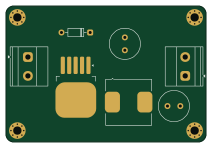
Buck converter
53 × 36 mm7 parts2LMIT0
Similar boards

Stack chan
stack-chan
50 × 50 mm33 parts2LApache-2.01.7k
Display Carrier
AxxAxx
35.6 × 58.2 mm5 parts2LGPL-3.01.7k
ControllerCurrentShuntAddOn
stuartpittaway
26 × 16.9 mm9 parts2LCC-BY-NC-4.01.1k
Module 16S PassiveBalanceAddOn
61 × 74 mm86 parts2LCC-BY-NC-4.01.1k
TemperaturePCB PANEL
116 × 75.5 mm178 parts2LCC-BY-NC-4.01.1k
ProgrammingAdapter
10.5 × 83 mm3 parts2LCC-BY-NC-4.01.1k