
Internet radio

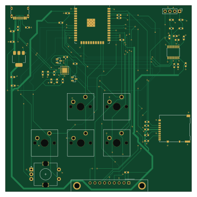
About the Internet radio PCB
Internet radio is an open source ESP32 PCB design by Amagami45, published on GitHub under the AGPL-3.0 license. It is a 2-layer board measuring 97.5 × 97.5 mm, with 52 components from 24 distinct parts.
Its main chip is the ESP32-WROOM-32E-N4, from the ESP32 family. Other key parts include the AMS1117-3.3, PCM5102AIPWR, CR2013-MI2120 and CP2102N-A02-GQFN24R. By type, the board carries 19 capacitors, 17 resistors, 6 switches, 5 ICs, 3 connectors and 2 transistors.
It belongs with the audio, rf & radio and iot & wireless designs in this gallery.
From the project
This project is about building an internet radio receiver which will change the audio output to analog, which will be transferred to an old FM radio (AIWA). From the radio, audio will come out to connected speakers.
This project is about building an internet radio receiver which will change the audio output to analog, which will be transferred to an old FM radio (AIWA). From the radio, audio will come out to connected speakers.
I have an old Aiwa, which can do only FM and AM frequencies, and most radio stations start to turn to DAB+ signal. So that's the main reason why I chose building this internet radio receiver. Also, I can listen to foreign countries' radio stations.
Main components on the Internet radio
Internet radio bill of materials (BOM)
52 components, 24 distinct parts — part numbers from the project's BOM.
| Qty | Part | Footprint | Refs |
|---|---|---|---|
| 1 | ESP32-WROOM-32E-N4 ESP32-WROOM-32 Espressif | ESP32-WROOM-32 | U1 |
| 1 | AMS1117-3.3 AMS | SOT-223-3_TabPin2 | U2 |
| 1 | PCM5102AIPWR PCM5102 Texas Instruments | TSSOP-20_4.4x6.5mm_P0.65mm | U3 |
| 1 | CR2013-MI2120 Generic | CR2013-MI2120 | U4 |
| 1 | CP2102N-A02-GQFN24R CP2102N-Axx-xQFN24 Silicon Labs | QFN-24-1EP_4x4mm_P0.5mm_EP2.6x2.6mm | U5 |
| 2 | BC847B BC847 Nexperia | SOT-23 | Q1, Q2 |
| 1 | USB_C_Receptacle_USB2.0_16P SHOU HAN | USB_C_Receptacle_HRO_TYPE-C-31-M-12 | J1 |
| 1 | DM3AT-SF-PEJM5 Micro_SD_Card Hirose | microSD_HC_Hirose_DM3AT-SF-PEJM5 | J2 |
| 1 | HEADER-1X4P-2.54 Conn_Coaxial_x2_Isolated Generic | PinHeader_1x04_P2.54mm_Vertical | J3 |
| 1 | EC11E1224404 RotaryEncoder_Switch ALPS | RotaryEncoder_Alps_EC11E-Switch_Vertical_H20mm | SW1 |
| 5 | MX-1.0U SW_Push Cherry | SW_Cherry_MX_1.00u_PCB | SW2, SW3, SW5, SW6, SW7 |
| 2 | CL10A225KP8NNNC 2.2μf SAMSUNG | C_0603_1608Metric | C1, C6 |
| 1 | CL10A105KB8NNNC 1uf SAMSUNG | C_0603_1608Metric | C2 |
| 9 | CL10B104KB8NNNC 100nf SAMSUNG | C_0603_1608Metric | C3, C4, C5, C9, C11, C12, C13, C19 +1 |
| 1 | CL10A105KB8NNNC 1μf SAMSUNG | C_0603_1608Metric | C7 |
| 2 | CL10A106MO8NNNC 10uf SAMSUNG | C_0603_1608Metric | C8, C10 |
| 2 | CL10B222KB8NNNC 2.2nf SAMSUNG | C_0603_1608Metric | C14, C15 |
| 2 | CL10A475KP8NNNC 4.7µf SAMSUNG | C_0603_1608Metric | C18, C21 |
| 2 | 0603WAF5101T5E 5.1k UNI-ROYAL | R_0603_1608Metric | R1, R2 |
| 4 | 0603WAF1002T5E 10k UNI-ROYAL | R_0603_1608Metric | R3, R6, R7, R8 |
Show 4 more
| Qty | Part | Footprint | Refs |
|---|---|---|---|
| 2 | 0603WAF4700T5E 470Ω UNI-ROYAL | R_0603_1608Metric | R4, R5 |
| 1 | 0603WAF4701T5E 4.7kΩ UNI-ROYAL | R_0603_1608Metric | R9 |
| 6 | 0603WAF1002T5E 10kΩ UNI-ROYAL | R_0603_1608Metric | R10, R13, R14, R15, R16, R17 |
| 2 | 0603WAF1001T5E 1kΩ UNI-ROYAL | R_0603_1608Metric | R11, R12 |
Internet radio design files
The KiCad project lives in the Amagami45/Internet-radio repository on GitHub; these links point at the commit this page was built from.
- LayoutAIWA cad/Aiwa internet.kicad_pcb
- SchematicAIWA cad/Aiwa internet.kicad_sch
- BOMBOM.csv
Internet radio: common questions
What microcontroller does the Internet radio use?
The Internet radio is built around the ESP32-WROOM-32E-N4, from the ESP32 family.
How big is the Internet radio PCB?
The Internet radio measures 97.5 × 97.5 mm, has 2 copper layers and is 1.6 mm thick.
How many components are on the Internet radio?
52 components, from 24 distinct parts, with part numbers taken from the project's own BOM. The full bill of materials is listed on this page.
Where can I download the Internet radio design files?
From the Amagami45/Internet-radio repository on GitHub, which has the KiCad layout, the schematic and the BOM; the links under Design files point to each one.
Can I use the Internet radio design in my own project?
Yes, under the terms of its AGPL-3.0 license, which Amagami45 chose for the repository.
Can I test firmware for the Internet radio without the hardware?
Yes. HardLabs builds a simulation of the board from its netlist and BOM, so you can run and debug ESP32 firmware against it before you order a PCB.
Similar boards
 ESP32
ESP32Open Book Abridged Edition
joeycastillo
85 × 115 mm65 parts2LCC-BY-SA-4.08.1k ESP32
ESP32Badge
atopile
56.3 × 39 mm239 parts4LMIT4.0k ESP32
ESP32Esp32 minimal
36.2 × 26.8 mm20 parts2LMIT4.0k ESP32
ESP32Racer
StuckAtPrototype
36 × 50.2 mm70 parts4LApache-2.03.8k ESP32
ESP32Controller
29 × 74 mm58 parts4LApache-2.03.8k ESP32
ESP32Bitaxe
skot
56.5 × 99.8 mm86 parts4LCERN-OHL-S-2.01.4k