
Taiko-Input

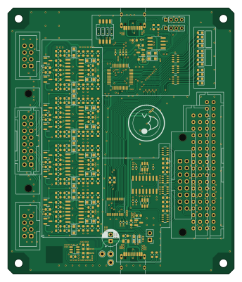
About the Taiko-Input PCB
Taiko-Input is an open source STM32 PCB design by AnalogDragon, published on GitHub under the Custom license license. It is a 2-layer board measuring 85 × 100 mm, with 235 components from 47 distinct parts.
Its main chip is the STM32G030C, from the STM32 family. Other key parts include the TL084, XC6206P332MR, CH552T, 74HC165 and CH340N. By type, the board carries 104 resistors, 63 capacitors, 40 diodes, 13 ICs, 10 connectors and 3 test points.
From the project
HID 太鼓输入硬件/太鼓控制器 Taiko IO Board / Taiko Controller
分为双鼓与单鼓硬件,双鼓设计用于街机或两个鼓的场景,单鼓的硬件则是双鼓硬件简单地切去一半输入前端设计的,在硬件上两者并无很大的差异。
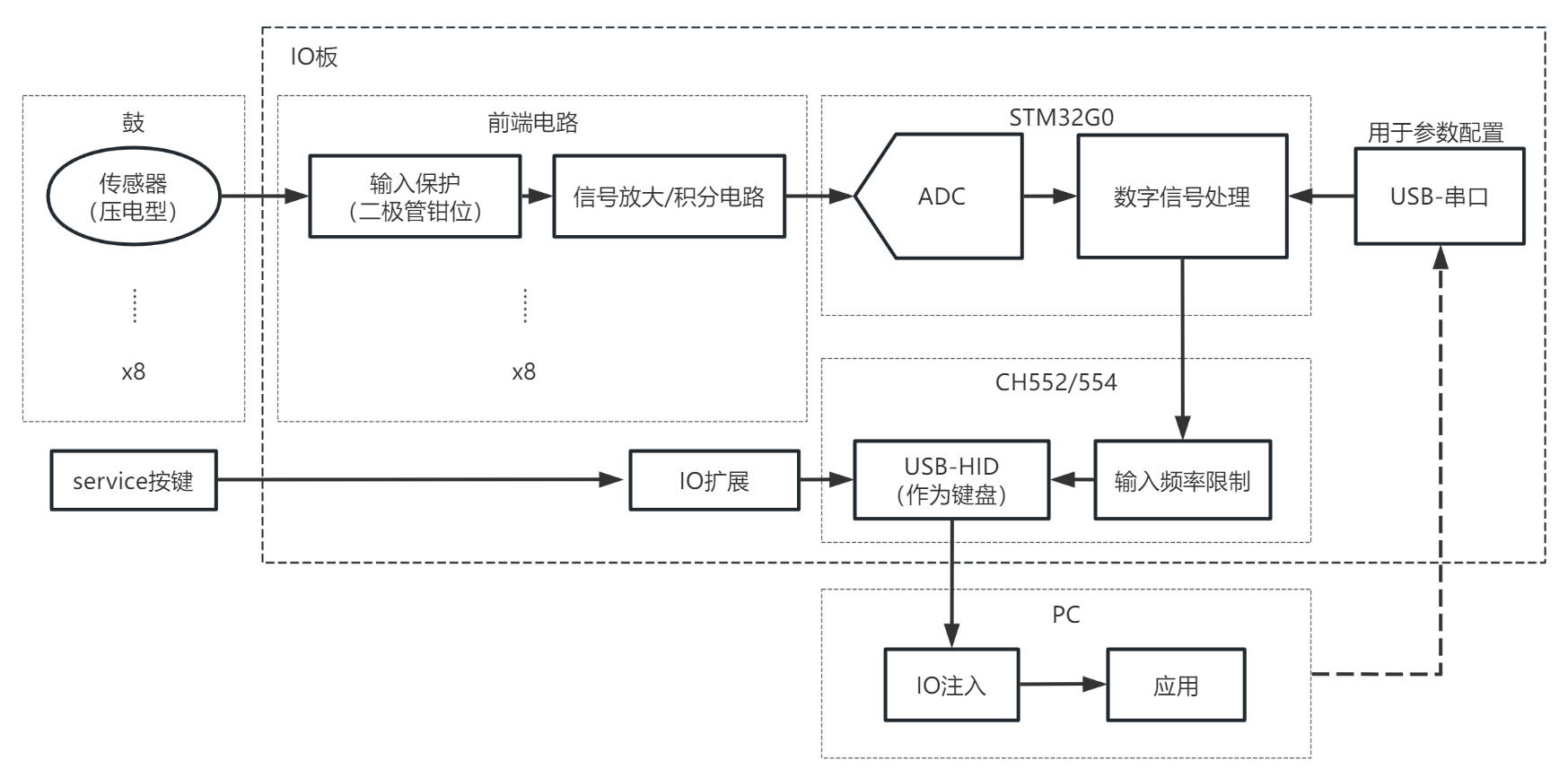
整体系统分为传感器(鼓)、前端、采样、USB、PC,其中前端、采样、USB三部分位于input硬件上。 除此之外还,有电源、滤波电路等未在结构图中体现。
前端电路采用了与SIF Board近似的设计,先进行信号的放大与积分,再限制输出。
由于来自压电传感器的信号带宽高且信号幅值小,不宜直接进行采样。前端电路将输入信号处理成便于采样的信号。 在示波器截图中,C1(黄色)为传感器输出,C3(红色)为经过前端电路处理后的信号,C2(蓝色)为程序识别后的输出。
硬件分为双鼓硬件和单鼓硬件,双鼓硬件为完整版的硬件,可以用于街机环境。 单鼓硬件为双鼓硬件删去一半输入电路的硬件,软件上兼容了更多的单人应用场景。
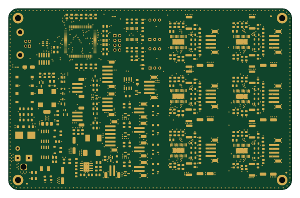
Main components on the Taiko-Input
Taiko-Input bill of materials (BOM)
235 components, 47 distinct parts — part numbers from the project's BOM.
| Qty | Part | Footprint | Refs |
|---|---|---|---|
| 4 | TL084 | SOIC-14_3.9x8.7mm_P1.27mm | U1, U2, U3, U4 |
| 1 | STM32G030C | LQFP-48_7x7mm_P0.5mm | U5 |
| 2 | XC6206P332MR | SOT-23 | U6, U13 |
| 1 | CH552T | SSOP-20_4.4x6.5mm_P0.65mm | U7 |
| 1 | 74HC165 | SOIC-16_3.9x9.9mm_P1.27mm | U8 |
| 1 | CH340N | SOIC-8_3.9x4.9mm_P1.27mm | U9 |
| 2 | SRV05-4 | SOT-23-6 | U10, U11 |
| 1 | SGM3204 | SOT-23-6 | U12 |
| 2 | Conn_02x08_Odd_Even | IDC-Header_2x08-1MP_P2.54mm_Latch6.5mm_Vertical | J1, J7 |
| 2 | Conn_02x04_Odd_Even | IDC-Header_2x04_P2.54mm_Vertical | J2, J3 |
| 2 | Conn_01x04 | PinSocket_1x04_P2.00mm_Vertical | J4, J5 |
| 1 | Conn_02x20_Odd_Even | B40B-XADSS-N-A | J8 |
| 2 | USB_C_Receptacle_USB2.0 | USB_C_Receptacle_HRO_TYPE-C-31-M-12 | J9, J10 |
| 1 | Conn_02x18_Odd_Even | B36B-XADSS-N-A | J11 |
| 1 | 0.5A/30V | Fuse_0805_2012Metric | F1 |
| 1 | SW_DIP_x04 | SW_DIP_SPSTx04_Slide_Copal_CHS-04B_W7.62mm_P1.27mm | SW1 |
| 3 | TestPoint | TestPoint_THTPad_D2.0mm_Drill1.0mm | TP1, TP2, TP3 |
| 8 | BAT54S | SOT-23 | D1, D2, D3, D4, D13, D14, D15, D16 |
| 16 | 1N4148WS | SOD_323_1 | D5, D6, D7, D8, D9, D10, D11, D12 +8 |
| 2 | 1N5819WS | SOD_323_1 | D25, D26 |
Show 27 more
| Qty | Part | Footprint | Refs |
|---|---|---|---|
| 2 | D_TVS | SOD_523_1 | D28, D29 |
| 6 | BLUE_LED | LED_0603_1608Metric | D32, D35, D36, D39, D40, D43 |
| 6 | RED_LED | LED_0603_1608Metric | D33, D34, D37, D38, D41, D42 |
| 8 | 2.2nF/50V | C_0603_1608Metric | C1, C2, C3, C4, C9, C10, C11, C12 |
| 9 | 4.7uF/16V | C_0603_1608Metric | C5, C6, C7, C8, C13, C14, C15, C16 +1 |
| 18 | 100nF/50V | C_0603_1608Metric | C17, C18, C19, C20, C21, C22, C23, C24 +10 |
| 8 | 10nF/50V | C_0603_1608Metric | C25, C26, C27, C28, C29, C30, C31, C32 |
| 6 | 10uF/16V | C_0603_1608Metric | C33, C42, C56, C57, C62, C63 |
| 2 | 22uF/6.3V | C_0603_1608Metric | C34, C43 |
| 2 | 1uF/25V | C_0402_1005Metric | C35, C39 |
| 7 | 100nF/50V | C_0402_1005Metric | C36, C37, C38, C40, C41, C52, C55 |
| 2 | 1nF/50V | C_0402_1005Metric | C53, C54 |
| 1 | 220uF/10V | CP_Radial_D6.3mm_P2.50mm | C61 |
| 8 | 1M | R_0603_1608Metric | R1, R2, R3, R4, R37, R38, R39, R40 |
| 8 | 3.3K | R_0603_1608Metric | R5, R6, R7, R8, R41, R42, R43, R44 |
| 8 | 200K | R_0603_1608Metric | R9, R11, R13, R15, R45, R47, R49, R51 |
| 9 | NC | R_0603_1608Metric | R10, R12, R14, R16, R46, R48, R50, R52 +1 |
| 8 | 100K | R_0603_1608Metric | R17, R19, R21, R23, R53, R55, R57, R59 |
| 9 | 0R | R_0603_1608Metric | R18, R20, R22, R24, R54, R56, R58, R60 +1 |
| 8 | 47R | R_0603_1608Metric | R25, R26, R27, R28, R61, R62, R63, R64 |
| 8 | 4.7K | R_0603_1608Metric | R29, R30, R31, R32, R65, R66, R67, R68 |
| 8 | 10K | R_0603_1608Metric | R33, R34, R35, R36, R69, R70, R71, R72 |
| 3 | 10K | C_0402_1005Metric | R73, R74, R75 |
| 4 | 5K1 | R_0603_1608Metric | R78, R79, R80, R81 |
| 16 | 1K | R_0603_1608Metric | R82, R83, R84, R85, R86, R87, R88, R89 +8 |
| 5 | 4.7K | R_Array_Convex_4x0603 | RN5, RN6, RN9, RN10, RN11 |
| 2 | 100R | R_Array_Convex_4x0603 | RN7, RN8 |
Taiko-Input design files
The KiCad project lives in the AnalogDragon/Taiko-Input repository on GitHub; these links point at the commit this page was built from.
Taiko-Input: common questions
What microcontroller does the Taiko-Input use?
The Taiko-Input is built around the STM32G030C, from the STM32 family.
How big is the Taiko-Input PCB?
The Taiko-Input measures 85 × 100 mm, has 2 copper layers and is 1.6 mm thick.
How many components are on the Taiko-Input?
235 components, from 47 distinct parts, with part numbers taken from the project's own BOM. The full bill of materials is listed on this page.
Where can I download the Taiko-Input design files?
From the AnalogDragon/Taiko-Input repository on GitHub, which has the KiCad layout, the schematic and the BOM; the links under Design files point to each one.
Can I use the Taiko-Input design in my own project?
It is published under Custom license, which limits how it may be reused; read the license before building on it.
Can I test firmware for the Taiko-Input without the hardware?
Yes. HardLabs builds a simulation of the board from its netlist and BOM, so you can run and debug STM32 firmware against it before you order a PCB.
Similar boards
 STM32
LumenPnP Motherboard
opulo-inc
149 × 95 mm296 parts4LCC-BY-SA-4.03.7k STM32
Base
google
52.3 × 52.3 mm36 parts2LApache-2.02.9k STM32
Type g
169 × 30 mm24 parts2LApache-2.02.9k STM32
Main panel
234 × 84 mm26 parts4LApache-2.02.9k STM32
Type a
150 × 30 mm14 parts2LApache-2.02.9k STM32
Type c
188 × 30 mm17 parts2LApache-2.02.9k