
Spectrum-Audio-Amp

About the Spectrum-Audio-Amp PCB
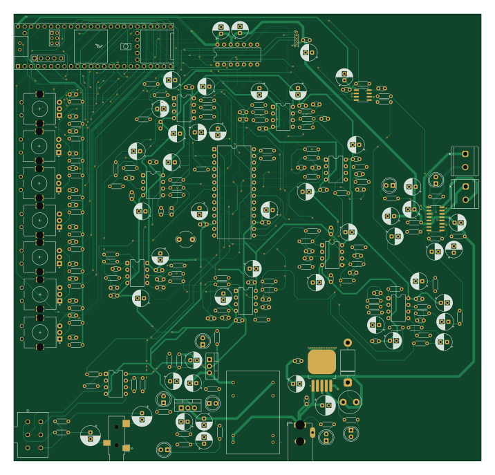
Spectrum-Audio-Amp is an open source NXP PCB design by anasarif23, published on GitHub. It is a 4-layer board measuring 178.8 × 171 mm, with 242 components from 59 distinct parts.
Its main chip is the Teensy4.1, from the NXP family. Other key parts include the NE5532, LM317_TO-220, LM337_TO220, LM2596S-5 and LMC835N. By type, the board carries 110 capacitors, 96 resistors, 11 ICs, 9 diodes, 7 switches and 5 connectors.
It belongs with the audio, test & measurement and displays & leds designs in this gallery.
From the project
Stereo audio preamp with EQ, spectrum display, and class-D power amplifier — designed in KiCad.
The first version of the schematic, completed while learning KiCad fundamentals. This version has some design mistakes that I identified during review, including [add specifics if you can — e.g. incorrect regulator pinout, missing decoupling capacitors, etc.]. I used Claude as a learning resource throughout this stage to understand regulator behavior, KiCad's schematic tools, and best practices for power supply design.
Main components on the Spectrum-Audio-Amp
Spectrum-Audio-Amp bill of materials (BOM)
242 components, 59 distinct parts.
| Qty | Part | Footprint | Refs |
|---|---|---|---|
| 3 | NE5532 | DIP-8_W7.62mm | U1, U6, U13 |
| 1 | LM317_TO-220 | TO-220-3_Vertical | U2 |
| 1 | LM337_TO220 | TO-220-3_Vertical | U3 |
| 1 | LM2596S-5 | TO-263-5_TabPin3 | U4 |
| 1 | LMC835N | DIP-28_W15.24mm | U5 |
| 1 | MSGEQ7 | SOIC-8_3.9x4.9mm_P1.27mm | U14 |
| 1 | Teensy4.1 | Teensy41 | U15 |
| 1 | SN74AHCT125N | DIP-14_W7.62mm | U16 |
| 1 | PAM8403D | SOIC-16_3.9x9.9mm_P1.27mm | U18 |
| 1 | SJ-3523-SMT | Jack_3.5mm_CUI_SJ-3523-SMT_Horizontal | J1 |
| 1 | Barrel_Jack | BarrelJack_GCT_DCJ200-10-A_Horizontal | J2 |
| 2 | Screw_Terminal_01x02 | TerminalBlock_CUI_TB007-508-02_1x02_P5.08mm_Horizontal | J3, J4 |
| 1 | Conn_01x06_Pin | PinHeader_1x06_P1.00mm_Vertical | J6 |
| 1 | DCWN03A-12 | DCWN03A12 | PS1 |
| 1 | 10k | POT_PDB182_BRN | RV1 |
| 7 | RotaryEncoder | RotaryEncoder_Alps_EC11E_Vertical_H20mm | SW1, SW2, SW3, SW4, SW5, SW6, SW7 |
| 1 | 1N5822 | D_DO-201AD_P15.24mm_Horizontal | D1 |
| 8 | LED | LED_D5.0mm | D2, D3, D4, D5, D6, D7, D8, D9 |
| 1 | FerriteBead | LairdTech_28C0236-0JW-10 | FB1 |
| 1 | 33uH | L_Radial_D8.7mm_P5.00mm_Fastron_07HCP | L1 |
Show 39 more
| Qty | Part | Footprint | Refs |
|---|---|---|---|
| 2 | 2.2uF | CP_Radial_D7.5mm_P2.50mm | C1, C2 |
| 11 | 1uF | CP_Radial_D6.3mm_P2.50mm | C3, C6, C16, C17, C51, C54, C88, C89 +3 |
| 7 | 0.1uF | CP_Radial_D6.3mm_P2.50mm | C4, C5, C15, C18, C63, C64, C91 |
| 1 | 220uF | CP_Radial_D7.5mm_P2.50mm | C7 |
| 22 | 100nF | C_Disc_D3.0mm_W1.6mm_P2.50mm | C8, C10, C11, C14, C43, C46, C48, C50 +14 |
| 1 | 220uF | CP_Radial_D6.3mm_P2.50mm | C9 |
| 22 | 10uF | CP_Radial_D6.3mm_P2.50mm | C12, C13, C44, C45, C47, C49, C52, C55 +14 |
| 3 | 0.47uF | CP_Radial_D6.3mm_P2.50mm | C19, C94, C107 |
| 2 | 0.033uF | C_Disc_D3.0mm_W1.6mm_P2.50mm | C20, C22 |
| 1 | 0.47uF | C_Disc_D3.0mm_W1.6mm_P2.50mm | C21 |
| 2 | 0.15uF | C_Disc_D3.0mm_W1.6mm_P2.50mm | C23, C25 |
| 2 | 0.015uF | C_Disc_D3.0mm_W1.6mm_P2.50mm | C24, C26 |
| 2 | 0.068uF | C_Disc_D3.0mm_W1.6mm_P2.50mm | C27, C29 |
| 2 | 0.0068uF | C_Disc_D3.0mm_W1.6mm_P2.50mm | C28, C30 |
| 2 | 0.022uF | C_Disc_D3.0mm_W1.6mm_P2.50mm | C31, C33 |
| 2 | 0.0033uF | C_Disc_D3.0mm_W1.6mm_P2.50mm | C32, C34 |
| 2 | 0.01uF | C_Disc_D3.0mm_W1.6mm_P2.50mm | C35, C37 |
| 2 | 0.0015uF | C_Disc_D3.0mm_W1.6mm_P2.50mm | C36, C38 |
| 2 | 0.0047uF | C_Disc_D3.0mm_W1.6mm_P2.50mm | C39, C41 |
| 4 | 680pF | C_Disc_D3.0mm_W1.6mm_P2.50mm | C40, C42, C53, C75 |
| 1 | 33pF | C_Disc_D3.0mm_W1.6mm_P2.50mm | C85 |
| 14 | 10nF | C_Disc_D3.0mm_W1.6mm_P2.50mm | C92, C93, C95, C96, C97, C98, C99, C100 +6 |
| 1 | 470uF | CP_Radial_D6.3mm_P2.50mm | C108 |
| 5 | 47k | R_Axial_DIN0204_L3.6mm_D1.6mm_P5.08mm_Horizontal | R1, R2, R3, R50, R53 |
| 2 | 22k | R_Axial_DIN0204_L3.6mm_D1.6mm_P5.08mm_Horizontal | R4, R10 |
| 4 | 100 | R_Axial_DIN0204_L3.6mm_D1.6mm_P5.08mm_Horizontal | R5, R6, R57, R62 |
| 2 | 1.8k | R_Axial_DIN0204_L3.6mm_D1.6mm_P5.08mm_Horizontal | R7, R8 |
| 2 | 240 | R_Axial_DIN0204_L3.6mm_D1.6mm_P5.08mm_Horizontal | R9, R13 |
| 2 | 1.2k | R_Axial_DIN0204_L3.6mm_D1.6mm_P5.08mm_Horizontal | R11, R12 |
| 26 | 100k | R_Axial_DIN0204_L3.6mm_D1.6mm_P5.08mm_Horizontal | R14, R16, R17, R18, R20, R21, R23, R24 +18 |
| 14 | 680 | R_Axial_DIN0204_L3.6mm_D1.6mm_P5.08mm_Horizontal | R15, R19, R22, R25, R28, R31, R34, R37 +6 |
| 4 | 82k | R_Axial_DIN0204_L3.6mm_D1.6mm_P5.08mm_Horizontal | R32, R35, R38, R41 |
| 2 | 62k | R_Axial_DIN0204_L3.6mm_D1.6mm_P5.08mm_Horizontal | R44, R47 |
| 4 | 470 | R_Axial_DIN0204_L3.6mm_D1.6mm_P5.08mm_Horizontal | R58, R60, R63, R66 |
| 2 | 6.8k | R_Axial_DIN0204_L3.6mm_D1.6mm_P5.08mm_Horizontal | R59, R65 |
| 1 | 200k | R_Axial_DIN0204_L3.6mm_D1.6mm_P5.08mm_Horizontal | R69 |
| 20 | 10k | R_Axial_DIN0204_L3.6mm_D1.6mm_P5.08mm_Horizontal | R70, R71, R72, R73, R75, R76, R78, R79 +12 |
| 1 | 2.2k | R_Axial_DIN0204_L3.6mm_D1.6mm_P5.08mm_Horizontal | R77 |
| 5 | 1.5k | R_Axial_DIN0204_L3.6mm_D1.6mm_P5.08mm_Horizontal | R90, R91, R92, R93, R94 |
Spectrum-Audio-Amp design files
The KiCad project lives in the anasarif23/Spectrum-Audio-Amp repository on GitHub; these links point at the commit this page was built from.
- LayoutAudio_Amplifier.kicad_pcb
- SchematicAudio_Amplifier.kicad_sch
Spectrum-Audio-Amp: common questions
What microcontroller does the Spectrum-Audio-Amp use?
The Spectrum-Audio-Amp is built around the Teensy4.1, from the NXP family.
How big is the Spectrum-Audio-Amp PCB?
The Spectrum-Audio-Amp measures 178.8 × 171 mm, has 4 copper layers and is 1.6 mm thick.
How many components are on the Spectrum-Audio-Amp?
242 components, from 59 distinct parts. The full bill of materials is listed on this page.
Where can I download the Spectrum-Audio-Amp design files?
From the anasarif23/Spectrum-Audio-Amp repository on GitHub, which has the KiCad layout and the schematic; the links under Design files point to each one.
Can I use the Spectrum-Audio-Amp design in my own project?
The repository has no license, so all rights stay with anasarif23. Use it as a reference, and ask the author before reusing the design.
Can I test firmware for the Spectrum-Audio-Amp without the hardware?
Yes. HardLabs builds a simulation of the board from its netlist and BOM, so you can run and debug NXP firmware against it before you order a PCB.
Similar boards
 NXP
NXP32Bit shift register
MaltWhiskey
100 × 54 mm56 parts4LNo license763 NXP
NXPMega-Cube-Board
200 × 54 mm100 parts4LNo license763 NXP
NXPMCL64
MicroCoreLabs
39.3 × 61.8 mm9 parts4LNo license532 NXP
NXPROM Emulator
21.5 × 37.1 mm5 parts2LNo license532 NXP
NXPMCLZ8
37.1 × 61.5 mm6 parts4LNo license532 NXP
NXPXTMAX
81 × 46 mm14 parts4LNo license532