
RelaisAddierer

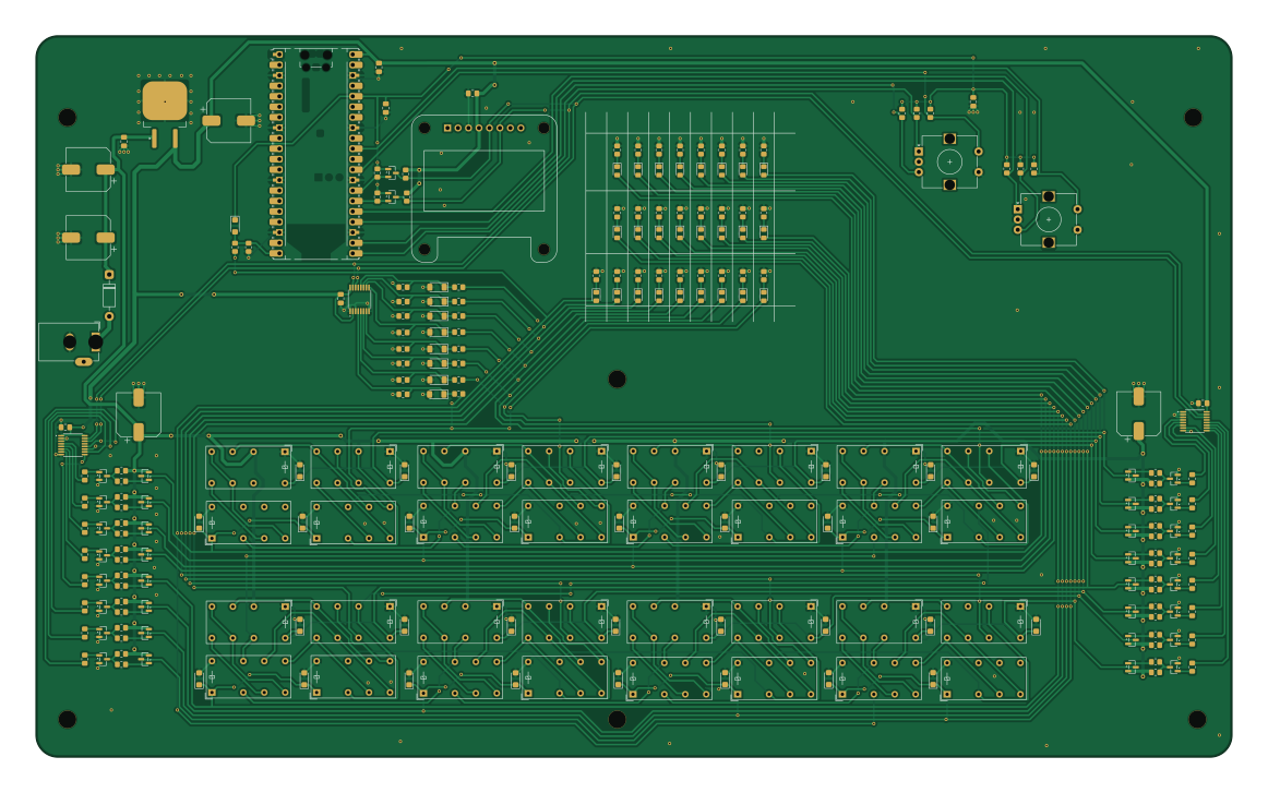
About the RelaisAddierer PCB
RelaisAddierer is an open source RP2040/RP2350 PCB design by apxco, published on GitHub. It is a 2-layer board measuring 290.1 × 175 mm, with 256 components from 23 distinct parts.
Its main chip is the RaspberryPi_Pico, from the RP2040/RP2350 family. Other key parts include the TCA9534 and uA7805. By type, the board carries 101 resistors, 67 diodes, 34 transistors, 32 relays, 13 capacitors and 4 ICs.
From the project
Kombination aus Mikrocontroller und 8-Bit Relais Addierer.
Kombination aus Mikrocontroller und 8-Bit Relais Addierer.
yC übernimmt die Ansteuerung der beiden Daten Bytes, die über die Relais Addiert werden und sorgt für die Ausgabe.
https://www.youtube.com/watch?v=YAB79SiROqY
04.09.2025 Initiale Idee zum Projekt, Erstellung Schaltbild und Leiterplatte Version 1.0 05.09.2025 Weiter an Leiterplatte, grobe Positionierung der Elemente, erste Schritte bei der Programmierung 06.09.2025 Bauteile zurecht gerückt, klappt nicht gut mit KiCad muss ich sagen. 07.09.2025 Layout steht soweit, keine wesentlichen Änderungen mehr vorgesehen an der Platine, jetzt…
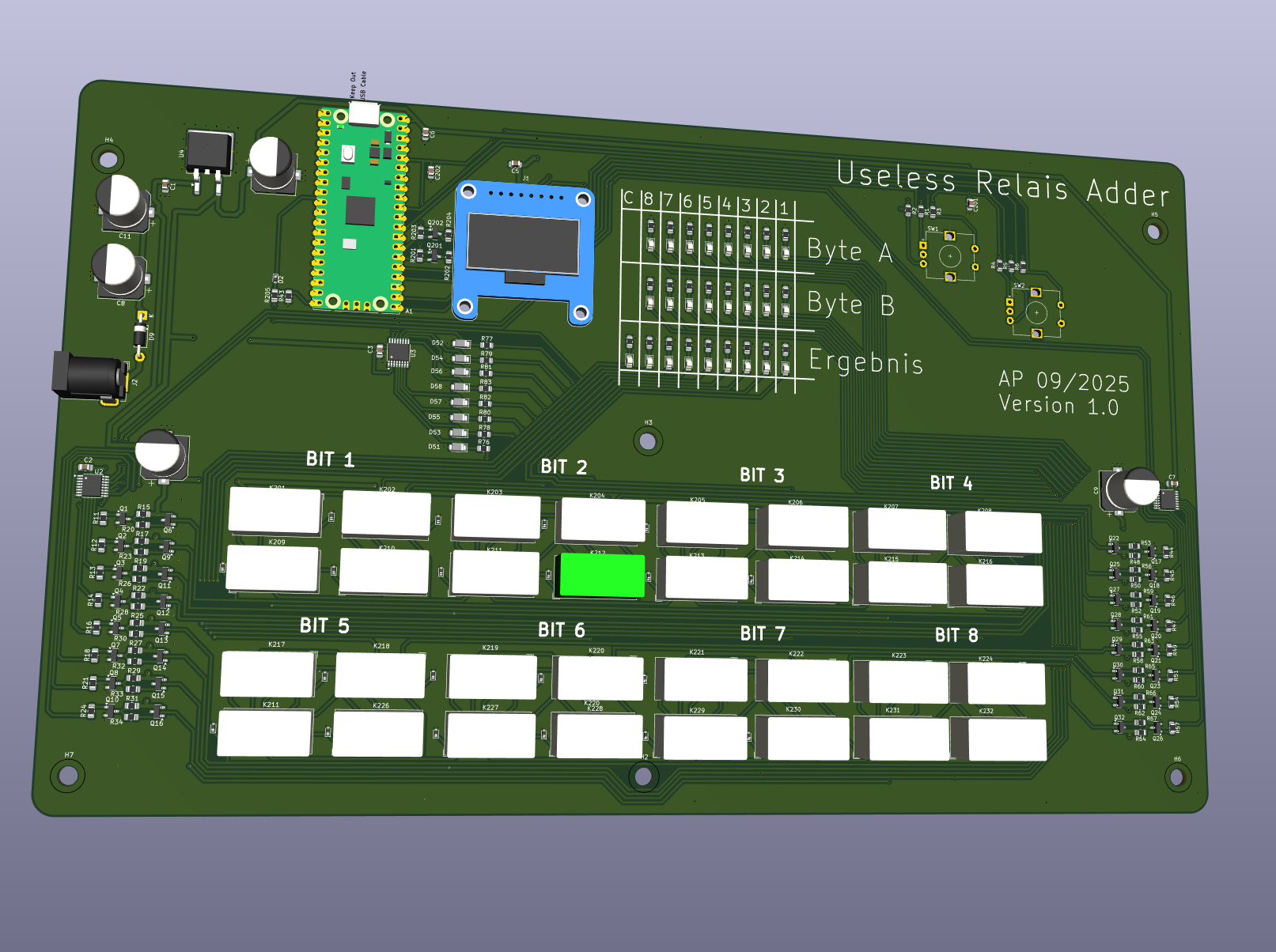
Main components on the RelaisAddierer
RelaisAddierer bill of materials (BOM)
256 components, 23 distinct parts.
| Qty | Part | Footprint | Refs |
|---|---|---|---|
| 3 | TCA9534 | TSSOP-16_4.4x5mm_P0.65mm | U1, U2, U3 |
| 1 | uA7805 | TO-263-2 | U4 |
| 1 | RaspberryPi_Pico | RaspberryPi_Pico_Common_Unspecified | A1 |
| 16 | BC847 | SOT-23 | Q1, Q2, Q3, Q4, Q5, Q7, Q8, Q10 +8 |
| 1 | PJM10H01PSA | SOT-23 | Q6 |
| 15 | DMP3099L | SOT-23 | Q9, Q11, Q12, Q13, Q14, Q15, Q16, Q22 +7 |
| 2 | BSS138 | SOT-23 | Q201, Q202 |
| 1 | Conn_01x08_Pin | Adafruit_SSD1306 | J1 |
| 1 | Barrel_Jack | BarrelJack_GCT_DCJ200-10-A_Horizontal | J2 |
| 32 | HK19F-DCxxV-SHC | Relay_DPDT_Finder_30.22 | K201, K202, K203, K204, K205, K206, K207, K208 +24 |
| 2 | RotaryEncoder_Switch | RotaryEncoder_Alps_EC12E-Switch_Vertical_H20mm | SW1, SW2 |
| 33 | 1N4148WT | D_SMF | D2, D201, D202, D203, D204, D205, D206, D207 +25 |
| 1 | 1N4007 | D_DO-41_SOD81_P10.16mm_Horizontal | D9 |
| 25 | LED | LED_0805_2012Metric_Pad1.15x1.40mm_HandSolder | D34, D35, D36, D37, D38, D39, D40, D41 +17 |
| 8 | BZD27C47 | D_MiniMELF | D51, D52, D53, D54, D55, D56, D57, D58 |
| 1 | 1uF | C_0805_2012Metric_Pad1.18x1.45mm_HandSolder | C1 |
| 7 | 100nF | C_0805_2012Metric_Pad1.18x1.45mm_HandSolder | C2, C3, C5, C6, C7, C201, C202 |
| 5 | 470uF | CP_Elec_10x12.5 | C8, C9, C10, C11, C12 |
| 26 | 10k | R_0805_2012Metric_Pad1.20x1.40mm_HandSolder | R1, R2, R3, R4, R5, R6, R15, R17 +18 |
| 41 | 1k | R_0805_2012Metric_Pad1.20x1.40mm_HandSolder | R7, R8, R9, R10, R35, R36, R37, R38 +33 |
Show 3 more
| Qty | Part | Footprint | Refs |
|---|---|---|---|
| 32 | 100R | R_0805_2012Metric_Pad1.20x1.40mm_HandSolder | R11, R12, R13, R14, R16, R18, R20, R21 +24 |
| 1 | 560 | R_0805_2012Metric_Pad1.20x1.40mm_HandSolder | R83 |
| 1 | 2,6k | R_0805_2012Metric_Pad1.20x1.40mm_HandSolder | R205 |
RelaisAddierer design files
The KiCad project lives in the apxco/Kicad repository on GitHub; these links point at the commit this page was built from.
RelaisAddierer: common questions
What microcontroller does the RelaisAddierer use?
The RelaisAddierer is built around the RaspberryPi_Pico, from the RP2040/RP2350 family.
How big is the RelaisAddierer PCB?
The RelaisAddierer measures 290.1 × 175 mm, has 2 copper layers and is 1.6 mm thick.
How many components are on the RelaisAddierer?
256 components, from 23 distinct parts. The full bill of materials is listed on this page.
Where can I download the RelaisAddierer design files?
From the apxco/Kicad repository on GitHub, which has the KiCad layout and the schematic; the links under Design files point to each one.
Can I use the RelaisAddierer design in my own project?
The repository has no license, so all rights stay with apxco. Use it as a reference, and ask the author before reusing the design.
Can I test firmware for the RelaisAddierer without the hardware?
Yes. HardLabs builds a simulation of the board from its netlist and BOM, so you can run and debug RP2040/RP2350 firmware against it before you order a PCB.
More boards in Kicad
 AVR/Arduino
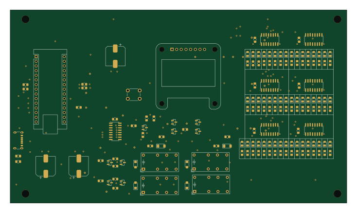
RelaisAdderII
183.3 × 105 mm160 parts2LNo license0
Transistor
152.4 × 76.2 mm115 parts2LNo license0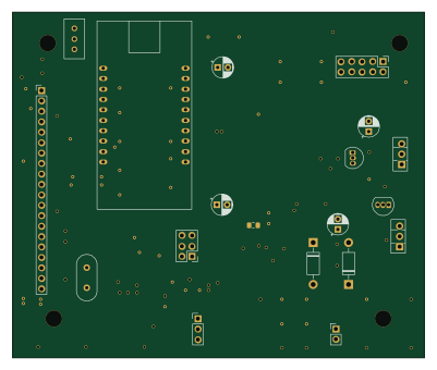 AVR/Arduino
DDS Modul 2
100 × 84 mm68 parts2LNo license0
H-Brücke
132.8 × 66.2 mm63 parts2LNo license0
OP-Damp
73.7 × 72.4 mm60 parts2LNo license0
Netzteilplatine duale Spannungsversorgung
161 × 86 mm46 parts2LNo license0 AVR/Arduino
Impulsgenerator
99 × 48.5 mm43 parts2LNo license0
Netzteilplatine
161 × 86 mm38 parts2LNo license0
Verst LM3886
54.3 × 57.3 mm31 parts2LNo license0 Raspberry Pi
Volksz2
65 × 56.5 mm30 parts2LNo license0
Freqgenklein
49.5 × 39.5 mm25 parts2LNo license0
Similar boards
 RP2040/RP2350
Open Book Abridged Edition
joeycastillo
85 × 115 mm29 parts2LCC-BY-SA-4.08.1k RP2040/RP2350
Corne
foostan
277.2 × 107.5 mm164 parts2LCC-BY-4.07.7k RP2040/RP2350
Corne
277.2 × 107.5 mm164 parts2LCC-BY-4.07.7k RP2040/RP2350
LogicAnalyzer
gusmanb
57 × 55.2 mm6 parts2LGPL-3.05.0k RP2040/RP2350
Jitx design
55.5 × 65 mm26 parts4LGPL-3.05.0k RP2040/RP2350
Main
google
98 × 71 mm102 parts2LApache-2.02.9k