
Main board

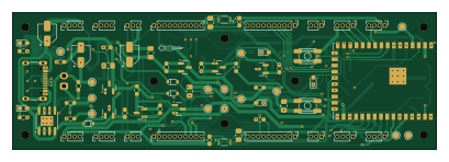
About the Main board
Main board is an open source ESP32 PCB design by arcticlula, published on GitHub under the MIT license. It is a 4-layer board measuring 102 × 33 mm, with 105 components from 35 distinct parts.
Its main chip is the ESP32-S2-WROVER-I, from the ESP32 family. Other key parts include the TL431DBZ, BH1750FVI, AP2112K-3.3, TP4056 and FS312MH. By type, the board carries 35 resistors, 18 capacitors, 11 diodes, 9 transistors, 7 ICs and 1 connector.
It belongs with the displays & leds and robotics & motion designs in this gallery.
From the project
Device that keeps track of a volleyball's game score (points and sets). Ideally it should be mounted on the net, since it has a display on the front and back and buttons on the sides.
Scoreboard system built around an ESP32-S3 main board with two hot-pluggable display slots and per-slot piezo audio.
Reference design deep-dive for the audio section: drv8662-buzzer-driver.md (design equations, BOM rationale, sigma-delta notes).
- [x] Buzzer nets — fixed in v3.0: BUZZER+/BUZZER- from the DRV8662 now reach both buzzer connectors (netlist-verified). - [ ] R21 (DRV8662 REXT) is 9.3 kΩ — non-stock value, use 9.31 kΩ or 10 kΩ. - [x] 0.8" score digit pinout — fixed in v3.0: the four 0.8" digits (U3/U5/U10/U12) use the dedicated 7Seg 0.8in Single symbol (correct pinout, Luis…
Main components on the Main board
Main board bill of materials (BOM)
105 components, 35 distinct parts — part numbers from the project's BOM.
| Qty | Part | Footprint | Refs |
|---|---|---|---|
| 1 | TL431DBZ | SOT-23 | U1 |
| 1 | ESP32-S2-WROVER-I | ESP32-S2-WROVER | U2 |
| 2 | BH1750FVI BH1750FVI-TR | XDCR_BH1750FVI-TR | U3, U4 |
| 1 | AP2112K-3.3 | SOT-23-5 | U5 |
| 1 | TP4056 | SOIC-8-1EP_3.9x4.9mm_P1.27mm_EP2.29x3mm | U6 |
| 1 | FS312MH | SOT-23-6_Handsoldering | U7 |
| 7 | AO3401A | SOT-23 | Q1, Q2, Q4, Q5, Q6, Q8, Q9 |
| 2 | AO3400A | SOT-23 | Q3, Q7 |
| 1 | USB_C_RECEPTACLE_USB2.0_16P USB_C_Receptacle_USB2.0_16P | USB_C_Receptacle_GCT_USB4105-xx-A_16P_TopMnt_Horizontal | J1 |
| 7 | SolderJumper_3_Open | SolderJumper-3_P1.3mm_Open_RoundedPad1.0x1.5mm_NumberLabels | AB_1, AB_2, AB_3, ALT_A1, ALT_B1, SW_1, SW_2 |
| 1 | CONN_01X02_PIN Conn_01x02_Pin | JST_XH_B2B-XH-A_1x02_P2.50mm_Vertical | BAT1 |
| 8 | CONN_01X04_PIN Conn_01x04_Pin | PinHeader_1x04_P1.27mm_Vertical | CA1, CA2, CA3, CA4, PWR1, PWR2, PWR3, PWR4 |
| 4 | CONN_01X10_PIN Conn_01x10_Pin | PinHeader_1x10_P1.27mm_Vertical | DD1, DD2, DD3, DD4 |
| 4 | Conn_01x03_Pin | PinHeader_1x03_P1.27mm_Vertical | SW_C1, SW_C2, SW_C3, SW_C4 |
| 3 | BAT20JFILM | SOD-323 | D1, D2, D10 |
| 5 | LED | LED_0603_1608Metric_Pad1.05x0.95mm_HandSolder | D3, D4, D5, D6, D7 |
| 3 | BAT20J | SOD-323 | D8, D9, D11 |
| 3 | 1UF 1uF | C_0805_2012Metric_Pad1.18x1.45mm_HandSolder | C1, C13, C16 |
| 8 | 0.1UF 0.1uF | C_0805_2012Metric_Pad1.18x1.45mm_HandSolder | C2, C3, C5, C6, C9, C10, C11, C12 |
| 3 | 10UF 10uF | CP_Elec_4x5.3 | C4, C15, C17 |
Show 15 more
| Qty | Part | Footprint | Refs |
|---|---|---|---|
| 2 | C | C_0805_2012Metric_Pad1.18x1.45mm_HandSolder | C7, C8 |
| 2 | 100NF 100nF | C_0603_1608Metric_Pad1.08x0.95mm_HandSolder | C14, C18 |
| 4 | 0 | R_0603_1608Metric_Pad0.98x0.95mm_HandSolder | R1, R5, R17, R18 |
| 4 | 10K 10k | R_0603_1608Metric_Pad0.98x0.95mm_HandSolder | R2, R6, R11, R30 |
| 3 | R | R_0603_1608Metric_Pad0.98x0.95mm_HandSolder | R3, R4, R29 |
| 2 | 5.1K | R_0603_1608Metric_Pad0.98x0.95mm_HandSolder | R7, R8 |
| 5 | 2.2K | R_0603_1608Metric_Pad0.98x0.95mm_HandSolder | R9, R15, R16, R26, R27 |
| 3 | R | C_0603_1608Metric_Pad1.08x0.95mm_HandSolder | R10, R13, R14 |
| 5 | 1M | R_0603_1608Metric_Pad0.98x0.95mm_HandSolder | R12, R24, R25, R28, R34 |
| 1 | 499 | C_0603_1608Metric_Pad1.08x0.95mm_HandSolder | R19 |
| 2 | 1k | C_0603_1608Metric_Pad1.08x0.95mm_HandSolder | R20, R23 |
| 2 | 4.7K 4.7k | C_0603_1608Metric_Pad1.08x0.95mm_HandSolder | R21, R22 |
| 1 | 100 | R_0603_1608Metric_Pad0.98x0.95mm_HandSolder | R31 |
| 2 | 1M | C_0603_1608Metric_Pad1.08x0.95mm_HandSolder | R32, R33 |
| 1 | 2K | R_0603_1608Metric_Pad0.98x0.95mm_HandSolder | R35 |
Main board design files
The KiCad project lives in the arcticlula/Netscore repository on GitHub; these links point at the commit this page was built from.
Main board: common questions
What microcontroller does the Main board use?
The Main board is built around the ESP32-S2-WROVER-I, from the ESP32 family.
How big is the Main board?
The Main board measures 102 × 33 mm, has 4 copper layers and is 1.6 mm thick.
How many components are on the Main board?
105 components, from 35 distinct parts, with part numbers taken from the project's own BOM. The full bill of materials is listed on this page.
Where can I download the Main board design files?
From the arcticlula/Netscore repository on GitHub, which has the KiCad layout, the schematic and the BOM; the links under Design files point to each one.
Can I use the Main board design in my own project?
Yes, under the terms of its MIT license, which arcticlula chose for the repository.
Can I test firmware for the Main board without the hardware?
Yes. HardLabs builds a simulation of the board from its netlist and BOM, so you can run and debug ESP32 firmware against it before you order a PCB.
More boards in Netscore
Similar boards
 ESP32
OSO-BOOK-B1
joeycastillo
85 × 115 mm65 parts2LCC-BY-SA-4.08.1k ESP32
Powertrain
byrantech
64 × 45.4 mm171 parts4LMIT4.3k ESP32
Badge
atopile
56.3 × 39 mm239 parts4LMIT4.0k ESP32
Esp32 minimal
36.2 × 26.8 mm20 parts2LMIT4.0k ESP32
Racer
StuckAtPrototype
36 × 50.2 mm70 parts4LApache-2.03.8k ESP32
Controller
29 × 74 mm58 parts4LApache-2.03.8k