
Rp2350-macropad

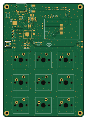
About the Rp2350-macropad PCB
Rp2350-macropad is an open source RP2040/RP2350 PCB design by arkandas, published on GitHub under the MIT license. It is a 2-layer board measuring 71.4 × 99.7 mm, with 80 components from 43 distinct parts.
Its main chip is the RP2350_60QFN, from the RP2040/RP2350 family. Other key parts include the W25Q32JVZPIQ, RT6150AGQW, JST DEBUG, ABM8-272-T3 and AHT20-F. By type, the board carries 22 capacitors, 19 resistors, 11 switches, 11 diodes, 7 ICs and 3 LEDs.
It belongs with the keyboards, displays & leds and sensors designs in this gallery.
From the project
RP2350A 3x3 mechanical macropad with a browser-programmable keymap and an on-board status LCD
A 3x3 mechanical macropad built around the Raspberry Pi RP2350A. It enumerates as a standard USB HID keyboard plus a USB CDC serial port, so each of the nine keys sends a configurable HID keycode and modifier combination. The key map is programmed over the serial port from a small web app, with no need to recompile or reflash the firmware to change it.
The board also drives a 1.14 inch ST7789 LCD that shows live temperature and humidity from an AHT20 sensor, basic system info (CPU clock, static RAM, uptime) and the current 3x3 key map. Three SK6805 RGB LEDs report status: power, caps lock…
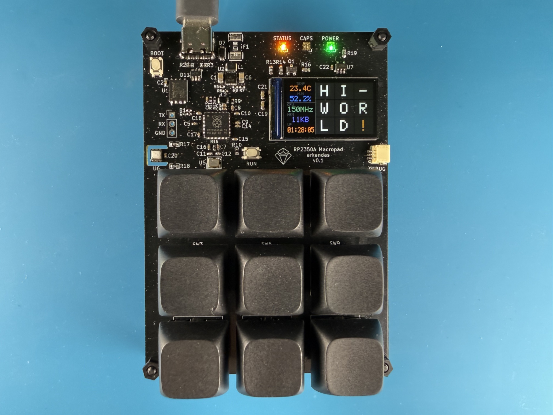
Main components on the Rp2350-macropad
Rp2350-macropad bill of materials (BOM)
80 components, 43 distinct parts — part numbers from the project's BOM.
| Qty | Part | Footprint | Refs |
|---|---|---|---|
| 1 | W25Q32JVZPIQ | WSON-8_L6.0-W5.0-P1.27-BL-EP | U1 |
| 1 | RT6150AGQW | WDFN-10_L3.0-W3.0-P0.50-BL-EP | U2 |
| 1 | JST DEBUG | CONN-SMD_SM03B-SRSS-TB-LF-SN-P | U3 |
| 1 | RP2350_60QFN | RP2350-QFN-60-1EP_7x7_P0.4mm_EP3.4x3.4mm_ThermalVias | U4 |
| 1 | ABM8-272-T3 | CRYSTAL-SMD_4P-L3.2-W2.5-BL | U5 |
| 1 | AHT20-F | SENSOR-SMD-6_AHT20 | U6 |
| 1 | 74AHCT1G125GV | SOT-23-5_L3.0-W1.7-P0.95-LS2.8-BL | U7 |
| 1 | MMBT2222ALT1G | SOT-23-3_L2.9-W1.3-P1.90-LS2.4-BR | Q1 |
| 1 | UART Pinout | PinHeader_1x03_P2.54mm_Vertical | J1 |
| 1 | 1.1A fuse | FUSE-SMD_L4.7-W3.4 | F1 |
| 1 | N114-2413THBIG01-H13 | LCD-SMD_1.14IPS-LCD | LCD1 |
| 1 | BOOT | KEY-SMD_4P-L4.2-W3.2-P2.20-LS5.1-TL | SW1 |
| 9 | MX2A-11NW SW_Push CHERRY | SW_Cherry_MX_PCB_1.00u | SW2, SW3, SW4, SW5, SW6, SW7, SW8, SW9 +1 |
| 1 | RUN | KEY-SMD_4P-L4.2-W3.2-P2.20-LS5.1-TL | SW11 |
| 1 | TYPE-C 16PIN | USB-C-SMD_TYPE-C-6PIN-2MD-073 | USB1 |
| 3 | SK6805-EC20 | LED-SMD_4P-L2.0-W2.0-BR | LED1, LED2, LED3 |
| 9 | 1N4148W | SOD-123F_L2.7-W1.6-LS3.8-RD | D1, D2, D3, D4, D5, D6, D8, D9 +1 |
| 1 | MBR120VLSFT1G | SOD-123F_L2.8-W1.8-LS3.7-RD | D7 |
| 1 | USBLC6-2SC6 | SOT-23-6_L2.9-W1.6-P0.95-LS2.8-BL | D11 |
| 1 | 2U2 2u2 | IND-SMD_L2.5-W2.0 | L1 |
Show 23 more
| Qty | Part | Footprint | Refs |
|---|---|---|---|
| 1 | 3.3U 3.3u | IND-SMD_L2.0-W1.6_AOTA-B201610S3R3-101-T | L2 |
| 2 | 47UF 47uF | C_0805_2012Metric | C1, C6 |
| 1 | 100N 100n | C0402 | C2 |
| 2 | 4.7UF 4.7uF | C_0402_1005Metric_small_pads | C3, C4 |
| 5 | 100N 100n | C_0402_1005Metric | C5, C9, C10, C20, C22 |
| 2 | 4.7UF 4.7uF | C_0402_1005Metric | C7, C8 |
| 2 | 15P 15p | C_0402_1005Metric | C11, C12 |
| 6 | 100n | C_0402_1005Metric | C13, C14, C15, C16, C17, C18 |
| 2 | 100NF 100nF | C_0603_1608Metric | C19, C21 |
| 2 | 1K | R_0402_1005Metric | R1, R15 |
| 2 | 5.1K | R0402 | R2, R3 |
| 1 | 10K 10k | R_0402_1005Metric | R4 |
| 2 | 100K 100k | R_0402_1005Metric | R5, R6 |
| 1 | 487K 487k | R_0402_1005Metric | R7 |
| 1 | 86.6K 86.6k | R_0402_1005Metric | R8 |
| 1 | 33OHM 33ohm | R_0402_1005Metric | R9 |
| 1 | 10K 10k | R0402 | R10 |
| 2 | 27OHM 27ohm | R_0402_1005Metric | R11, R12 |
| 1 | 10K | R_0603_1608Metric | R13 |
| 1 | 1K | R_0603_1608Metric | R14 |
| 1 | 22OHM 22ohm | R_0603_1608Metric | R16 |
| 2 | 4.7K 4.7k | R0603 | R17, R18 |
| 1 | 100OHM 100ohm | R_0603_1608Metric | R19 |
Rp2350-macropad design files
The KiCad project lives in the arkandas/rp2350-macropad repository on GitHub; these links point at the commit this page was built from.
Rp2350-macropad: common questions
What microcontroller does the Rp2350-macropad use?
The Rp2350-macropad is built around the RP2350_60QFN, from the RP2040/RP2350 family.
How big is the Rp2350-macropad PCB?
The Rp2350-macropad measures 71.4 × 99.7 mm, has 2 copper layers and is 1 mm thick.
How many components are on the Rp2350-macropad?
80 components, from 43 distinct parts, with part numbers taken from the project's own BOM. The full bill of materials is listed on this page.
Where can I download the Rp2350-macropad design files?
From the arkandas/rp2350-macropad repository on GitHub, which has the KiCad layout, the schematic and the BOM; the links under Design files point to each one.
Can I use the Rp2350-macropad design in my own project?
Yes, under the terms of its MIT license, which arkandas chose for the repository.
Can I test firmware for the Rp2350-macropad without the hardware?
Yes. HardLabs builds a simulation of the board from its netlist and BOM, so you can run and debug RP2040/RP2350 firmware against it before you order a PCB.
Similar boards
 RP2040/RP2350
Open Book Abridged Edition
joeycastillo
85 × 115 mm29 parts2LCC-BY-SA-4.08.1k RP2040/RP2350
Corne
foostan
277.2 × 107.5 mm164 parts2LCC-BY-4.07.7k RP2040/RP2350
Corne
277.2 × 107.5 mm164 parts2LCC-BY-4.07.7k RP2040/RP2350
LogicAnalyzer
gusmanb
57 × 55.2 mm6 parts2LGPL-3.05.0k RP2040/RP2350
Jitx design
55.5 × 65 mm26 parts4LGPL-3.05.0k RP2040/RP2350
Pro V2
kata0510
290.1 × 130 mm270 parts2LMIT2.3k