
SmartKnob

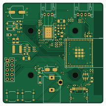
About the SmartKnob PCB
SmartKnob is an open source ESP32 PCB design by aryanthomare, published on GitHub. It is a 4-layer board measuring 54 × 54 mm, with 65 components from 40 distinct parts.
Its main chip is the ESP32-S3-MINI-1-N8, from the ESP32 family. Other key parts include the TPS54202DDCR, AP2112K-3.3TRG1, DRV8316CRRGFR and USBLC6-2SC6. By type, the board carries 25 capacitors, 20 resistors, 5 ICs, 5 connectors, 5 diodes and 2 switches.
It belongs with the iot & wireless and robotics & motion designs in this gallery.
From the project
A brushless gimbal motor sits under the knob. By driving it with the right torque at every angle, the firmware makes the same physical knob feel like a stepped volume dial, a smooth scroll wheel or a switch with hard end stops, and changes that feel on the fly as you switch tasks
A brushless gimbal motor sits under the knob. By driving it with the right torque at every angle, the firmware makes the same physical knob feel like a stepped volume dial, a smooth scroll wheel or a switch with hard end stops, and changes that feel on the fly as you switch tasks on the PC. The knob talks to a small Windows tray app over USB or Bluetooth LE, and works on its own as a media volume knob when the app isn't running.
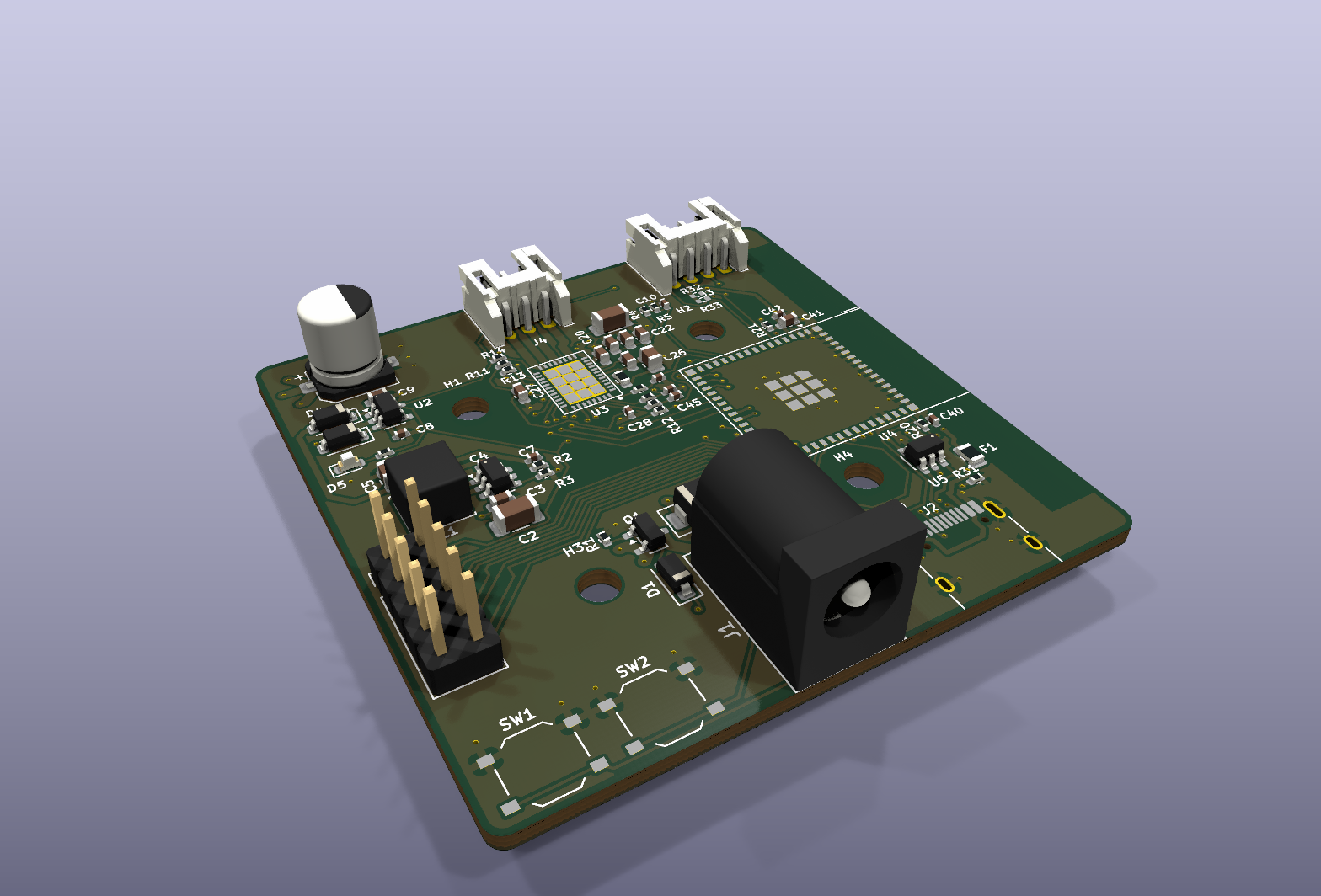
Main components on the SmartKnob
SmartKnob bill of materials (BOM)
65 components, 40 distinct parts — part numbers from the project's BOM.
| Qty | Part | Footprint | Refs |
|---|---|---|---|
| 1 | TPS54202DDCR | SOT-23-6 | U1 |
| 1 | AP2112K-3.3TRG1 | SOT-23-5 | U2 |
| 1 | DRV8316CRRGFR | TI_RGF0040E_VQFN-40-1EP_5x7mm_P0.5mm_EP3.7x5.7mm_ThermalVias | U3 |
| 1 | ESP32-S3-MINI-1-N8 | ESP32-S2-MINI-1 | U4 |
| 1 | USBLC6-2SC6 | SOT-23-6 | U5 |
| 1 | DMP3099L-7 | SOT-23 | Q1 |
| 1 | C84007 DC-005C-20A (5.5x2.1) | BarrelJack_Hroparts_DC-005C-20A_Horizontal | J1 |
| 1 | TYPE-C-31-M-12 | USB_C_Receptacle_HRO_TYPE-C-31-M-12 | J2 |
| 1 | C157926 ENCODER (S4B-PH-K-S) | JST_PH_S4B-PH-K_1x04_P2.00mm_Horizontal | J3 |
| 1 | C157929 MOTOR (S3B-PH-K-S) | JST_PH_S3B-PH-K_1x03_P2.00mm_Horizontal | J4 |
| 1 | BREAKOUT 2x5 | PinHeader_2x05_P2.54mm_Vertical | J5 |
| 1 | C20978 500mA PTC | Fuse_0805_2012Metric | F1 |
| 1 | C318884 RESET | SW_Push_1P1T_XKB_TS-1187A | SW1 |
| 1 | C318884 BOOT | SW_Push_1P1T_XKB_TS-1187A | SW2 |
| 1 | BZT52C15 | D_SOD-123 | D1 |
| 1 | SMAJ16A | D_SMA | D2 |
| 2 | B5819W | D_SOD-123 | D3, D4 |
| 1 | C2286 Red (PWR) | LED_0603_1608Metric | D5 |
| 1 | 15UH 15uH | L_Sunlord_SWPA5040S | L1 |
| 1 | C294520 100uF 35V | CP_Elec_6.3x7.7 | C1 |
Show 20 more
| Qty | Part | Footprint | Refs |
|---|---|---|---|
| 2 | C13585 10uF 50V | C_1206_3216Metric | C2, C23 |
| 4 | C14663 100nF 50V | C_0603_1608Metric | C3, C20, C21, C22 |
| 4 | 100NF 100nF | C_0402_1005Metric | C4, C10, C28, C42 |
| 3 | C45783 22uF 25V | C_0805_2012Metric | C5, C6, C26 |
| 1 | C107010 75pF C0G | C_0402_1005Metric | C7 |
| 2 | 1UF 1uF | C_0402_1005Metric | C8, C40 |
| 2 | 10UF 10uF | C_0603_1608Metric | C9, C41 |
| 2 | C15849 1uF 50V | C_0603_1608Metric | C24, C27 |
| 1 | C1622 47nF 50V | C_0603_1608Metric | C25 |
| 3 | C1555 22pF C0G | C_0402_1005Metric | C43, C44, C45 |
| 5 | C25744 10k | R_0402_1005Metric | R1, R12, R14, R20, R21 |
| 2 | C25741 100k 1% | R_0402_1005Metric | R2, R4 |
| 1 | C274352 13.3k 1% | R_0402_1005Metric | R3 |
| 1 | C25744 10k 1% | R_0402_1005Metric | R5 |
| 1 | 1k | R_0402_1005Metric | R6 |
| 1 | 22R | R_0603_1608Metric | R10 |
| 3 | 5.1K 5.1k | R_0402_1005Metric | R11, R30, R31 |
| 1 | C25741 100k | R_0402_1005Metric | R13 |
| 3 | 330R | R_0402_1005Metric | R22, R23, R24 |
| 2 | 4.7k DNP | R_0402_1005Metric | R32, R33 |
SmartKnob design files
The KiCad project lives in the aryanthomare/SmartKnob repository on GitHub; these links point at the commit this page was built from.
SmartKnob: common questions
What microcontroller does the SmartKnob use?
The SmartKnob is built around the ESP32-S3-MINI-1-N8, from the ESP32 family.
How big is the SmartKnob PCB?
The SmartKnob measures 54 × 54 mm, has 4 copper layers and is 1.6 mm thick.
How many components are on the SmartKnob?
65 components, from 40 distinct parts, with part numbers taken from the project's own BOM. The full bill of materials is listed on this page.
Where can I download the SmartKnob design files?
From the aryanthomare/SmartKnob repository on GitHub, which has the KiCad layout, the schematic and the BOM; the links under Design files point to each one.
Can I use the SmartKnob design in my own project?
The repository has no license, so all rights stay with aryanthomare. Use it as a reference, and ask the author before reusing the design.
Can I test firmware for the SmartKnob without the hardware?
Yes. HardLabs builds a simulation of the board from its netlist and BOM, so you can run and debug ESP32 firmware against it before you order a PCB.
Similar boards
 ESP32
OSO-BOOK-B1
joeycastillo
85 × 115 mm65 parts2LCC-BY-SA-4.08.1k ESP32
Powertrain
byrantech
64 × 45.4 mm171 parts4LMIT4.3k ESP32
Esp32 minimal
atopile
36.2 × 26.8 mm20 parts2LMIT4.0k ESP32
Badge
56.3 × 39 mm239 parts4LMIT4.0k ESP32
Racer
StuckAtPrototype
36 × 50.2 mm70 parts4LApache-2.03.8k ESP32
Controller
29 × 74 mm58 parts4LApache-2.03.8k