
TestSRAM

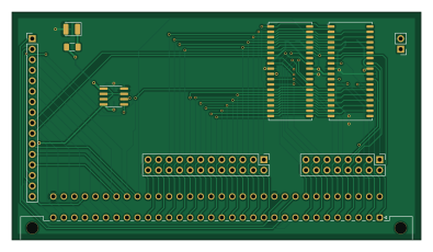
About the TestSRAM PCB
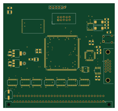
TestSRAM is an open source PCB design by aslak3, published on GitHub under the GPL-2.0 license. It is a 2-layer board measuring 98.6 × 54.9 mm, with 15 components from 11 distinct parts.
Other key parts include the IS61C5128AL-10KLI and AT24CS64-SSHM. By type, the board carries 5 connectors, 3 ICs, 3 capacitors, 3 resistors and 1 diode.
It belongs with the retro computing and sensors designs in this gallery.
From the project
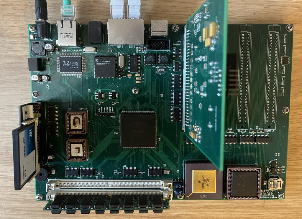
MC68030 based expandable computer design
The specification for MAXI030, a MC68030 based computer, is as follows:
A core "glue" that is wired to master the 32 bit busses Glue is provided by an EPF10K130EQC240-1 FPGA A 68030 coupled with a 68882 512K x 16 flashes in the form of 2 x SST39SF040 in PLCC32 2 x 72 pin SIMM slots with a controller implemented in the FPGA A SC26C94 QUART with the following arrangements of the four serial ports: Two on RJ45 at RS-232 levels following the standard Cisco pinnout One for my Amiga 600 keyboard on an RJ11 And a TTL header for debug and the bring-up Onboard 10Mbit/s Ethernet using a RTL8019AS A…
Main components on the TestSRAM
TestSRAM bill of materials (BOM)
15 components, 11 distinct parts.
| Qty | Part | Footprint | Refs |
|---|---|---|---|
| 2 | IS61C5128AL-10KLI | SOJ-36_10.16x23.49mm_P1.27mm | U1, U2 |
| 1 | AT24CS64-SSHM | SOIC-8_3.9x4.9mm_P1.27mm | U3 |
| 1 | DIN_41612_3x32_MIDI020_CARD | DIN41612_C_2x32_Male_Horizontal_THT | J1 |
| 1 | Conn_01x16 | PinHeader_1x16_P2.54mm_Vertical | J2 |
| 1 | Conn_02x08_Odd_Even | PinHeader_2x08_P2.54mm_Vertical | J3 |
| 1 | Conn_02x12_Odd_Even | PinHeader_2x12_P2.54mm_Vertical | J4 |
| 1 | Conn_01x02 | PinHeader_1x02_P2.54mm_Vertical | J5 |
| 1 | LED | LED_1210_3225Metric | D1 |
| 3 | 0.1u | C_1206_3216Metric | C1, C2, C3 |
| 1 | 1K | R_1206_3216Metric | R1 |
| 2 | 4.7K | R_1206_3216Metric | R2, R3 |
TestSRAM design files
The KiCad project lives in the aslak3/MAXI030 repository on GitHub; these links point at the commit this page was built from.
TestSRAM: common questions
How big is the TestSRAM PCB?
The TestSRAM measures 98.6 × 54.9 mm, has 2 copper layers and is 1.6 mm thick.
How many components are on the TestSRAM?
15 components, from 11 distinct parts. The full bill of materials is listed on this page.
Where can I download the TestSRAM design files?
From the aslak3/MAXI030 repository on GitHub, which has the KiCad layout and the schematic; the links under Design files point to each one.
Can I use the TestSRAM design in my own project?
Yes, under the terms of its GPL-2.0 license, which aslak3 chose for the repository.
More boards in MAXI030
Similar boards

Sensor smd
scottbez1
40 × 20 mm5 parts2LApache-2.04.2k
Sensors
StuckAtPrototype
15.2 × 9 mm14 parts4LApache-2.03.8k
Microphone
Mentra-Community
5.5 × 6.1 mm6 parts2LMIT1.2k
TemperaturePCB PANEL
stuartpittaway
116 × 75.5 mm178 parts2LCC-BY-NC-4.01.1k
Rgb to hdmi
hoglet67
77 × 97 mm67 parts2LGPL-3.01.0k
Analog
53.9 × 23.2 mm33 parts2LGPL-3.01.0k