
Printer+Sticks

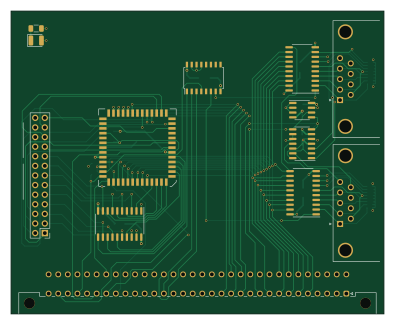
About the Printer+Sticks PCB
Printer+Sticks is an open source PCB design by aslak3, published on GitHub under the GPL-2.0 license. It is a 4-layer board measuring 98.6 × 80 mm, with 24 components from 13 distinct parts.
Other key parts include the 74LS139, AT24CS64-SSHM, MC68230, 74HC244 and 74LS574. By type, the board carries 7 ICs, 7 capacitors, 7 resistors, 2 connectors and 1 diode.
It belongs with the retro computing and sensors designs in this gallery.
From the project
MC68030 based expandable computer design
The specification for MAXI030, a MC68030 based computer, is as follows:
A core "glue" that is wired to master the 32 bit busses Glue is provided by an EPF10K130EQC240-1 FPGA A 68030 coupled with a 68882 512K x 16 flashes in the form of 2 x SST39SF040 in PLCC32 2 x 72 pin SIMM slots with a controller implemented in the FPGA A SC26C94 QUART with the following arrangements of the four serial ports: Two on RJ45 at RS-232 levels following the standard Cisco pinnout One for my Amiga 600 keyboard on an RJ11 And a TTL header for debug and the bring-up Onboard 10Mbit/s Ethernet using a RTL8019AS A…
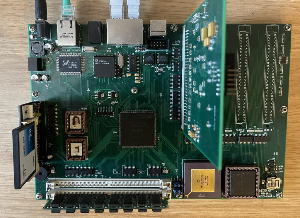
Main components on the Printer+Sticks
Printer+Sticks bill of materials (BOM)
24 components, 13 distinct parts.
| Qty | Part | Footprint | Refs |
|---|---|---|---|
| 1 | 74LS139 | SOIC-16W_5.3x10.2mm_P1.27mm | U1 |
| 1 | AT24CS64-SSHM | SOIC-8_3.9x4.9mm_P1.27mm | U2 |
| 1 | MC68230 | PLCC-52 | U3 |
| 1 | 74HC244 | SO-20_5.3x12.6mm_P1.27mm | U4 |
| 2 | 74LS574 | SO-20_5.3x12.6mm_P1.27mm | U5, U6 |
| 1 | MCP3428 | SOIC-14_3.9x8.7mm_P1.27mm | U7 |
| 1 | DIN_41612_3x32_MIDI020_CARD | DIN41612_C_2x32_Male_Horizontal_THT | J1 |
| 1 | Conn_02x13_Odd_Even | PinHeader_2x13_P2.54mm_Vertical | J2 |
| 1 | LED | LED_1210_3225Metric | D1 |
| 7 | 0.1u | C_1206_3216Metric | C1, C2, C3, C4, C5, C6, C7 |
| 1 | 1K | R_1206_3216Metric | R1 |
| 4 | 4.7K | R_1206_3216Metric | R2, R3, R4, R5 |
| 2 | 10K | R_Cat16-8 | RN1, RN2 |
Printer+Sticks design files
The KiCad project lives in the aslak3/MAXI030 repository on GitHub; these links point at the commit this page was built from.
Printer+Sticks: common questions
How big is the Printer+Sticks PCB?
The Printer+Sticks measures 98.6 × 80 mm, has 4 copper layers and is 1.6 mm thick.
How many components are on the Printer+Sticks?
24 components, from 13 distinct parts. The full bill of materials is listed on this page.
Where can I download the Printer+Sticks design files?
From the aslak3/MAXI030 repository on GitHub, which has the KiCad layout and the schematic; the links under Design files point to each one.
Can I use the Printer+Sticks design in my own project?
Yes, under the terms of its GPL-2.0 license, which aslak3 chose for the repository.
More boards in MAXI030
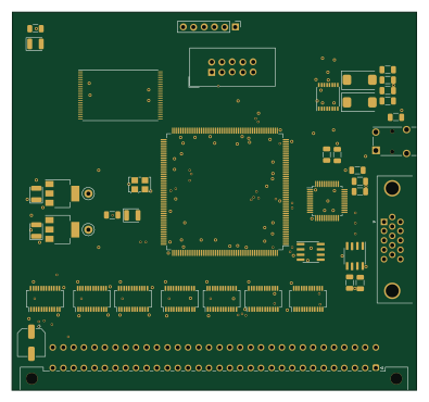
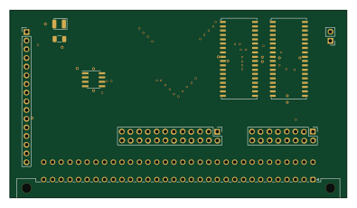
Similar boards

Sensor smd
scottbez1
40 × 20 mm5 parts2LApache-2.04.2k
Sensors
StuckAtPrototype
15.2 × 9 mm14 parts4LApache-2.03.8k
Microphone
Mentra-Community
5.5 × 6.1 mm6 parts2LMIT1.2k
TemperaturePCB PANEL
stuartpittaway
116 × 75.5 mm178 parts2LCC-BY-NC-4.01.1k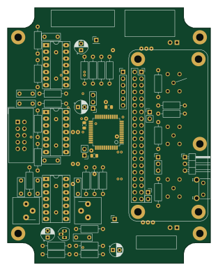
Rgb to hdmi
hoglet67
77 × 97 mm67 parts2LGPL-3.01.0k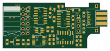
Analog
53.9 × 23.2 mm33 parts2LGPL-3.01.0k