
Adjustable-DC-DC-Buck-Converter

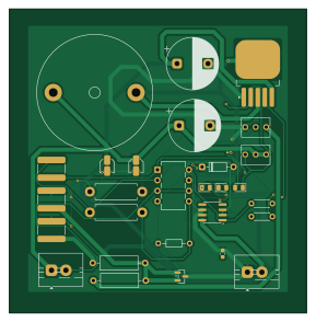
About the Adjustable-DC-DC-Buck-Converter PCB
Adjustable-DC-DC-Buck-Converter is an open source PCB design by bharat-ops77, published on GitHub under the GPL-3.0 license. It is a 2-layer board measuring 72 × 73.5 mm, with 29 components from 20 distinct parts.
Other key parts include the L78L05_SO8, XL4015, TL431DBZ and LM358. By type, the board carries 8 resistors, 7 capacitors, 4 ICs, 4 diodes, 1 fuse and 1 inductor.
It belongs with the power & battery designs in this gallery.
From the project
An open-source, high-efficiency DC-DC step-down buck converter schematic designed in KiCad. It features Constant Voltage (CV) and Constant Current (CC) control, making it ideal for battery charging, LED driving, and benchtop power supply projects.
An open-source, high-efficiency DC-DC step-down buck converter schematic designed in KiCad. It features Constant Voltage (CV) and Constant Current (CC) control, making it ideal for battery charging, LED driving, and benchtop power supply projects.
Core IC: XL4015 Step-Down DC-DC Converter (180 kHz PWM). Control Modes: Constant Voltage (CV): Precision output voltage regulation using RV2. Constant Current (CC): Adjustable current limit control using RV1. Precision Voltage Reference: Built-in L78L05 + TL431 voltage reference circuit for stable current limit thresholds. Low-side Current Sensing…
Main components on the Adjustable-DC-DC-Buck-Converter
Adjustable-DC-DC-Buck-Converter bill of materials (BOM)
29 components, 20 distinct parts.
| Qty | Part | Footprint | Refs |
|---|---|---|---|
| 1 | L78L05_SO8 | SOIC-8_3.9x4.9mm_P1.27mm | U1 |
| 1 | XL4015 | TO-263-5_TabPin3 | U2 |
| 1 | TL431DBZ | SOT-23 | U3 |
| 1 | LM358 | DIP8_300 | U4 |
| 1 | Fuse | Fuse_0603_1608Metric | F1 |
| 2 | Screw_Terminal_01x02 | TerminalBlock_MaiXu_MX126-5.0-02P_1x02_P5.00mm | Input1, Output1 |
| 2 | 10k | Potentiometer_Bourns_3266Y_Vertical | RV1, RV2 |
| 1 | D_Schottky | D_DO-35_SOD27_P7.62mm_Horizontal | D1 |
| 3 | LED | LED_0805_2012Metric | D2, D3, D4 |
| 1 | 40uH | L_Radial_D27.9mm_P20.07mm_Vishay_IHB-3 | L1 |
| 2 | 10uF | C_Elec_3x5.4 | C1, C5 |
| 2 | 470uF | CP_Radial_D12.5mm_P7.50mm | C2, C6 |
| 3 | 1uF | C_1825_4564Metric_Pad1.57x6.80mm_HandSolder | C3, C4, C7 |
| 1 | 2.2k | R_Axial_DIN0309_L9.0mm_D3.2mm_P12.70mm_Horizontal | R1 |
| 1 | 7.5k | R_Axial_DIN0309_L9.0mm_D3.2mm_P12.70mm_Horizontal | R2 |
| 1 | 270 | R_Axial_DIN0411_L9.9mm_D3.6mm_P12.70mm_Horizontal | R3 |
| 1 | 90.9k | R_Axial_DIN0411_L9.9mm_D3.6mm_P12.70mm_Horizontal | R4 |
| 1 | 10k | R_Axial_DIN0204_L3.6mm_D1.6mm_P7.62mm_Horizontal | R5 |
| 1 | 0.05 | R_0201_0603Metric_Pad0.64x0.40mm_HandSolder | R6 |
| 2 | 1k | R_Axial_DIN0204_L3.6mm_D1.6mm_P5.08mm_Horizontal | R7, R8 |
Adjustable-DC-DC-Buck-Converter design files
The KiCad project lives in the bharat-ops77/Adjustable-DC-DC-Buck-Converter repository on GitHub; these links point at the commit this page was built from.
Adjustable-DC-DC-Buck-Converter: common questions
How big is the Adjustable-DC-DC-Buck-Converter PCB?
The Adjustable-DC-DC-Buck-Converter measures 72 × 73.5 mm, has 2 copper layers and is 1.6 mm thick.
How many components are on the Adjustable-DC-DC-Buck-Converter?
29 components, from 20 distinct parts. The full bill of materials is listed on this page.
Where can I download the Adjustable-DC-DC-Buck-Converter design files?
From the bharat-ops77/Adjustable-DC-DC-Buck-Converter repository on GitHub, which has the KiCad layout and the schematic; the links under Design files point to each one.
Can I use the Adjustable-DC-DC-Buck-Converter design in my own project?
Yes, under the terms of its GPL-3.0 license, which bharat-ops77 chose for the repository.
Similar boards

EinkPDA screen
TalismanDesign
95 × 54 mm27 parts2LApache-2.02.0k
Stack chan
stack-chan
50 × 50 mm33 parts2LApache-2.01.7k
Display Carrier
AxxAxx
35.6 × 58.2 mm5 parts2LGPL-3.01.7k
ProgrammingAdapter
stuartpittaway
10.5 × 83 mm3 parts2LCC-BY-NC-4.01.1k
TemperaturePCB PANEL
116 × 75.5 mm178 parts2LCC-BY-NC-4.01.1k
Module 16S PassiveBalanceAddOn
61 × 74 mm86 parts2LCC-BY-NC-4.01.1k